


An equipment designer needs a USB-C service port at the enclosure, but the cable plugged into that port may also need to stay connected while the machine is handled. A panel mount secures the receptacle to the enclosure. A screw lock retains a plug at a compatible mating interface. These are two separate fixing jobs.
Goochain develops FPC ribbon cable assemblies for both layouts. Its panel-mount extension uses an internal USB-C male plug and an enclosure-mounted female port; its screw-locking FPC cable is specified around the mating hardware on the equipment. The starting point is to mark where insertion forces and cable movement should be carried in the finished assembly.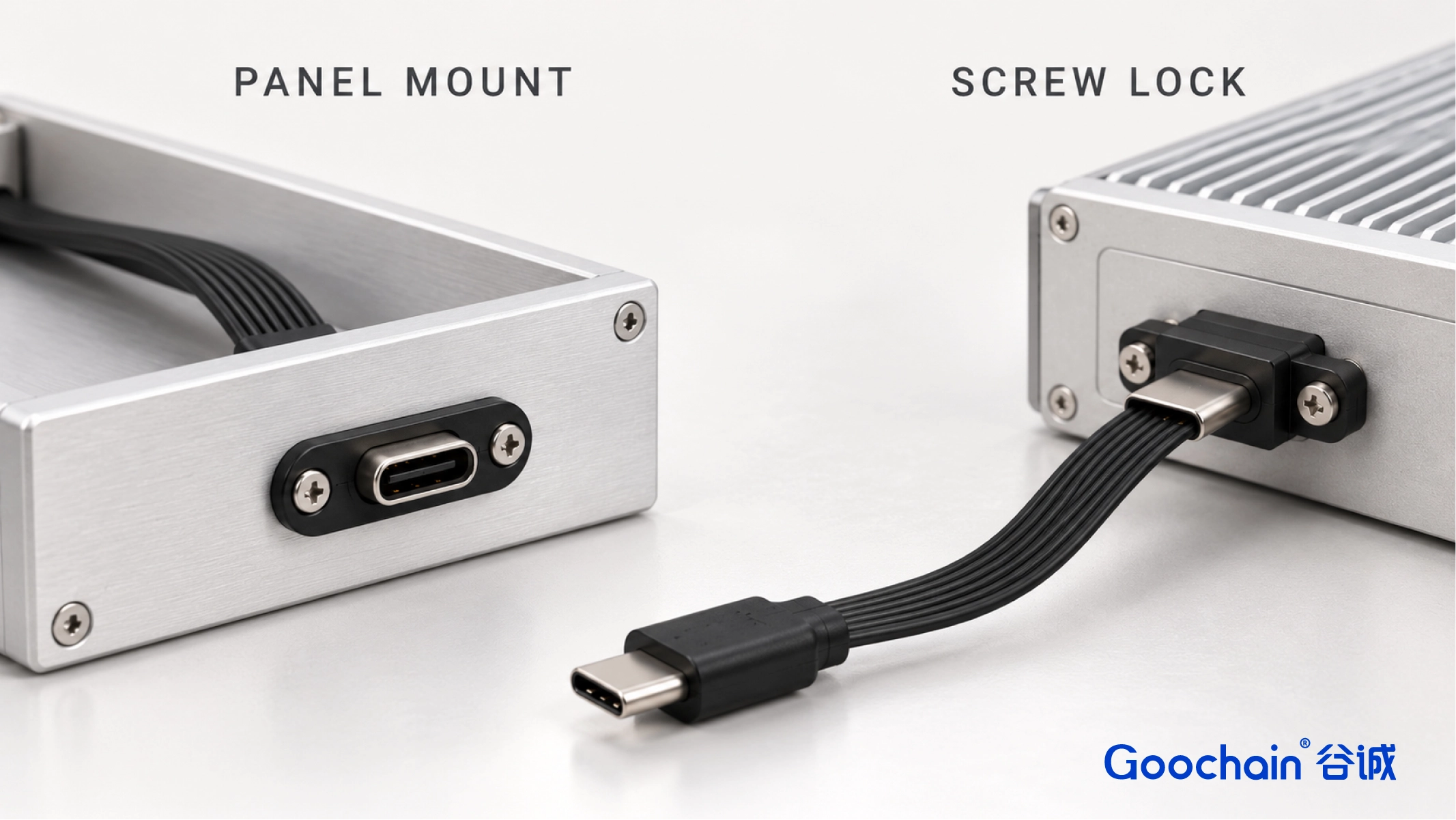
A fixed panel port is useful where an operator connects and removes an external cable. The receptacle flange or bracket transfers those handling forces into the enclosure. The USB-C panel mount FPC extension is a reference layout: the female port is accessible outside, and the FPC takes the connection to an internal male plug.
A retained plug addresses a different problem. The screw-locking USB-C FPC cable uses mechanical fixing at a compatible mating interface, with a flat route selected for the equipment. A plain USB-C opening has no screw retention merely because the plug has a screw. A design can use a panel-mounted socket with a locking plug only when the socket assembly also provides matching fixing points.
| Design question | Panel mount | Screw locking |
|---|---|---|
| Part held in place | Female receptacle at enclosure | Mating plug at compatible interface |
| Drawing inputs | Cutout, hole pattern, panel thickness, rear depth | Screw location, thread, engagement, tool access |
| Cable route | FPC behind the panel to internal port | FPC support and exit near retained plug |
| Typical reason | Repeated front access without loading the internal port | Retained connection in installed equipment |
First check the external plug against the actual front panel. A recessed opening or nearby connector can prevent its housing from seating fully even when the USB-C insert aligns. Put the cutout, receptacle position, mounting holes and panel thickness on the same drawing.
Behind the panel, allow for the connector body, fasteners, tool access and the FPC transition. Show the internal USB-C port, plug orientation and cable route around boards, bosses and covers. The finished length should follow that installed route without tension or an unsupported fold at the connector.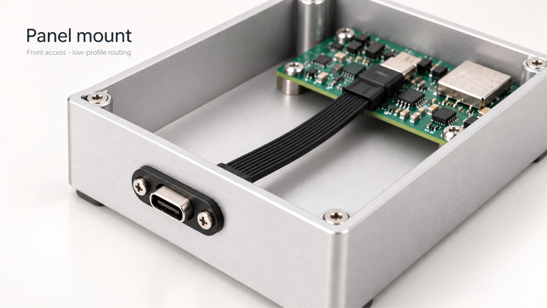
Identify the mating equipment and provide its drawing before choosing a locking housing. The screw position, thread and usable engagement must match the receiving points, and the plug must seat correctly before the fastener is tightened. USB-IF defines single- and dual-screw locking arrangements, but the words “screw locking” alone do not establish which interface a device uses.
Check whether a tool can reach the screw after the surrounding brackets and covers are fitted. Specify support for the FPC near the plug as well. Locking the connector should not transfer cable movement into a thin, unsupported transition.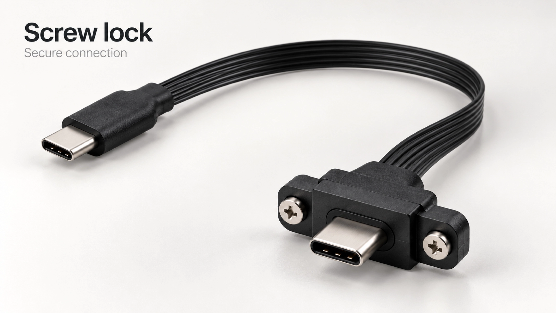
Neither a mounting flange nor retention screws establish an IP rating, a vibration result or an electrical speed. If sealing, pull force or vibration matters, name the method and acceptance condition for the complete installed assembly. Record the mating hardware and mounting condition used in the test.
Data, charging and any display function also need their own specification. A panel extension adds a connector interface and cable length to the path; the host, internal FPC assembly, external cable and device should be evaluated together. For a locking cable, evaluate the selected connector arrangement and length with its intended equipment.
For a useful quotation, send the panel or mating-interface drawing, internal port location, connector genders and orientations, FPC route and finished length. Add the required data and power functions, any display mode, test conditions and forecast quantity. State which screws or brackets are supplied with the cable and which belong to the equipment.
Goochain can review the connector and FPC layout, prepare samples for fit and functional checks, and quote production against an approved drawing. Contact Goochain with your drawing so the mounting hardware and the cable assembly can be reviewed as one installed connection.
Yes, if the receptacle assembly has the matching threaded fixing points and the plug can seat fully. A panel mount alone does not provide them.
Begin with a supported panel receptacle and check access for the actual external plug. Add plug retention if the installed cable must remain secured.
No. Those requirements need a specified complete assembly and an agreed test in its intended installation.
Yes. Goochain can review those details against the enclosure and mating-interface drawings, then confirm the selected assembly by sample evaluation.


 English
 简体中文
简体中文  Deutsche
  Italian
  français
  Español
  Nederlands
  日本語
日本語  한국어
한국어  عربى
عربى  português
  Türk
Türk 

