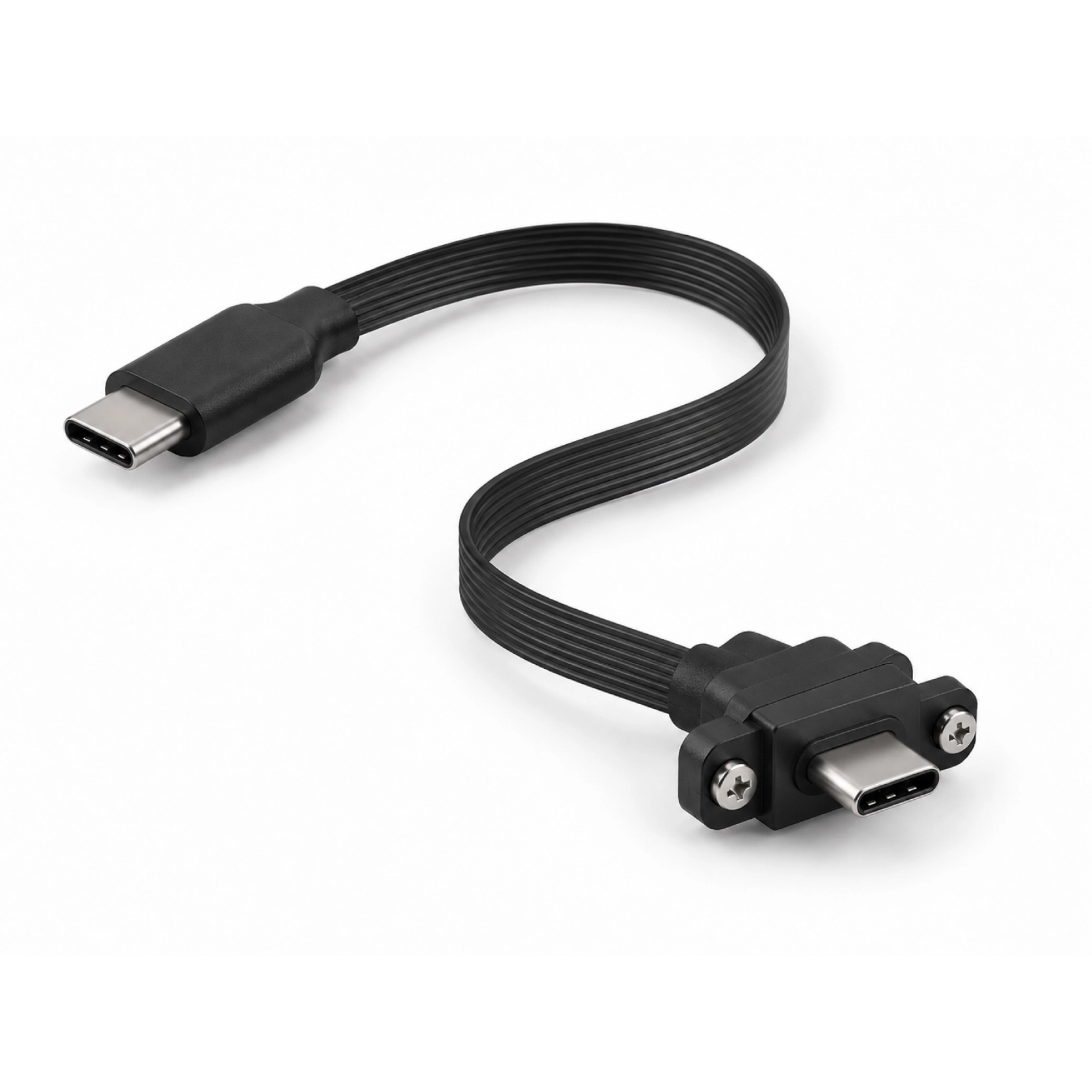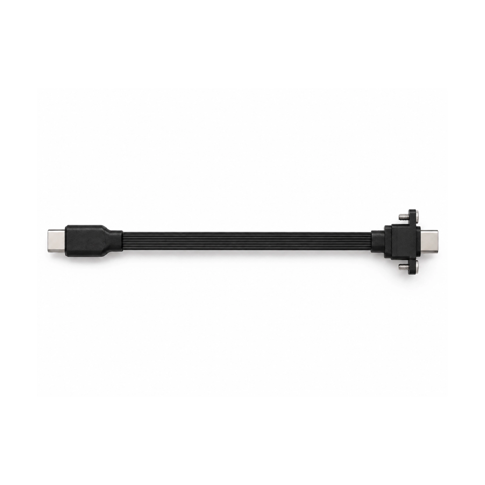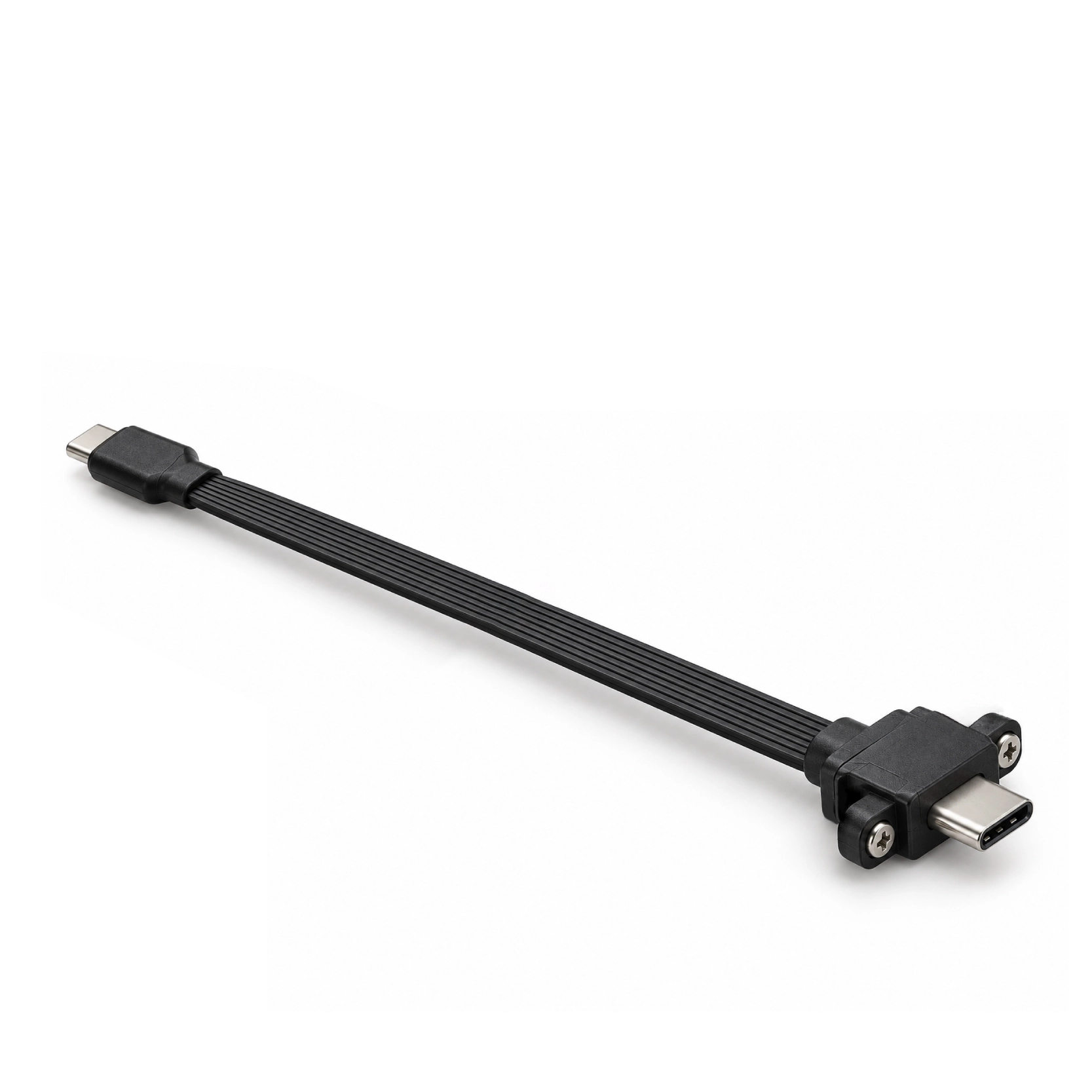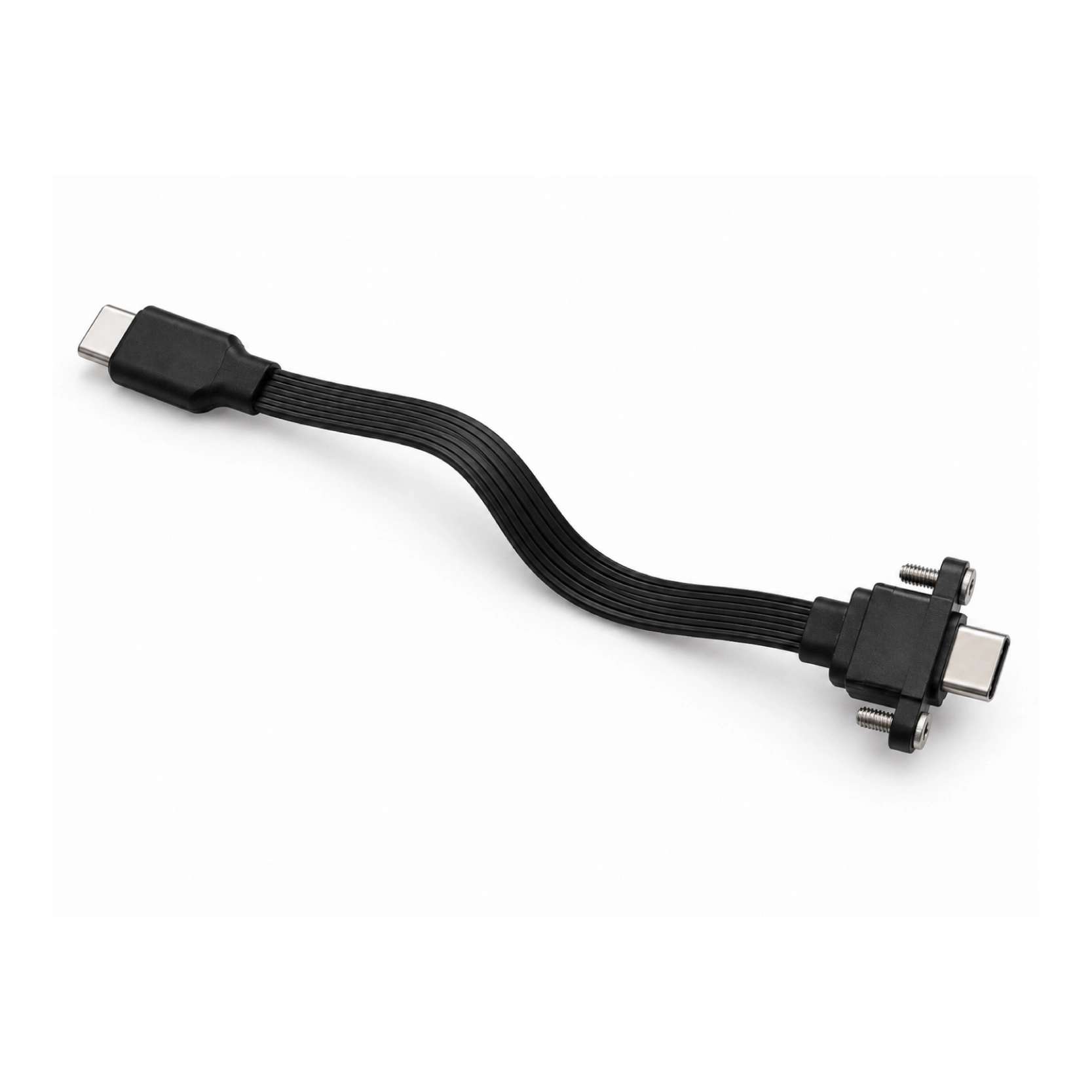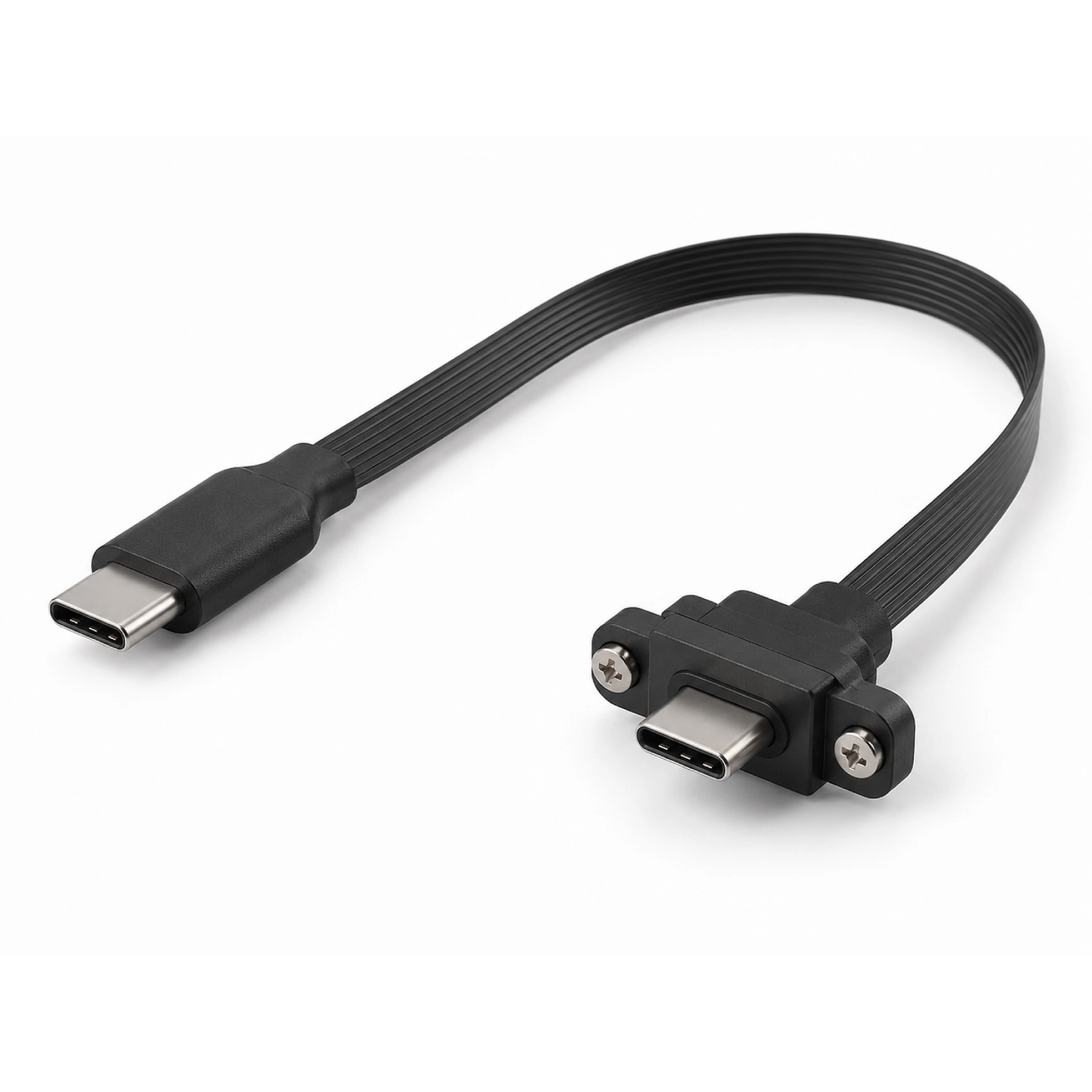


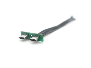
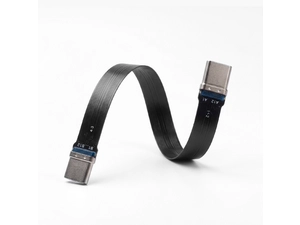
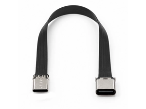
A flat USB-C cable assembly with mechanical screw retention for OEM equipment that requires a more secure connection than a standard friction-fit plug.
Goochain manufactures custom screw-locking USB-C FPC cables for industrial and OEM equipment where a standard friction-fit USB-C connection does not provide the required mechanical retention. The locking arrangement can be developed at one end or both ends, while the flat FPC route is customized around the equipment housing, PCB position and available assembly space. Thread specification, screw spacing, engagement length, connector housing and cable restraint are reviewed together so the mechanical interface matches the receiving equipment. For B2B projects, Goochain supports drawing review, sample development, installation evaluation and production inspection to the approved specification.
Goochain manufactures screw-locking USB-C FPC cables for equipment that requires mechanical retention at the USB-C connection. The locking hardware secures the connector to a compatible mating interface, while the flat flexible printed circuit follows the available cable route inside or alongside the housing.
Locking can be specified at one end or both ends. The connector arrangement, screw geometry and FPC outline are developed around the receiving equipment. Dongguan Goochain Technology Co., Ltd. supplies these custom OEM assemblies from Dongguan, China, with mechanical and electrical requirements defined for the selected configuration.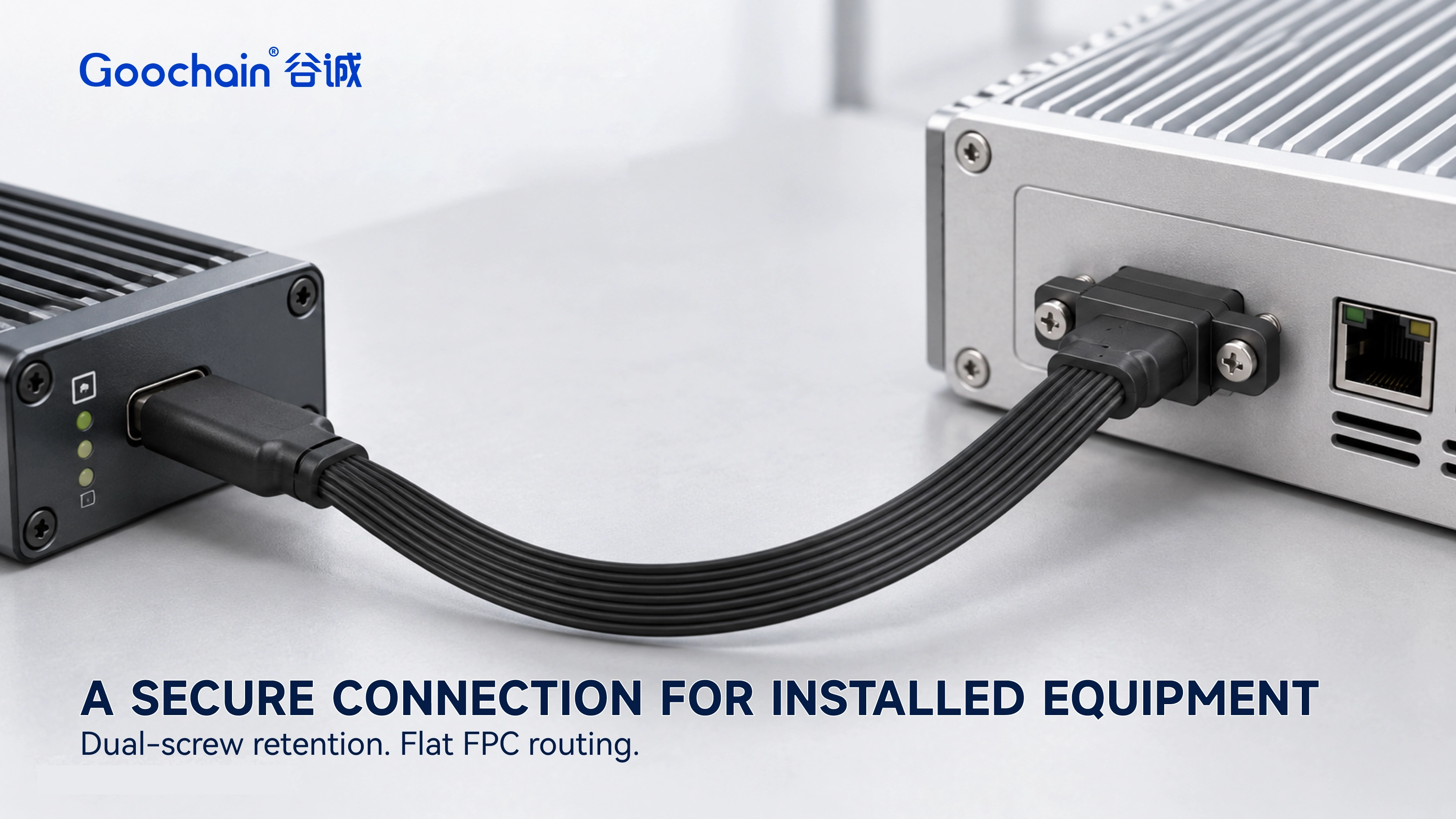
| Item | Specification |
|---|---|
| Brand | Goochain |
| Interface | USB-C with a defined screw-locking arrangement |
| Cable structure | Flexible printed circuit (FPC) assembly |
| Locking ends | One end or both ends, as specified |
| Connector configuration | Connector gender, orientation and opposite end to the approved drawing |
| Mechanical match | Thread specification, screw spacing and engagement length to the mating interface |
| Length and FPC outline | Customized to the installed route |
| Cable support | Restraint and connector-transition space defined by the installation |
| Electrical performance | Data rate, power and any video function specified independently |
| Validation | Mechanical and electrical checks to the agreed configuration and test requirements |
| Supply type | Custom OEM cable assembly |
In industrial controllers, inspection equipment and installed systems, cables may be handled during assembly or servicing. A screw-locking arrangement adds a defined mechanical attachment where the connector needs to remain retained. The receiving equipment must provide matching fixing points; the USB-C opening alone is not enough.
This differs from securing a socket to an enclosure. A USB-C Panel Mount FPC Cable fixes the receptacle to the panel. Screw locking retains the mating plug at its compatible interface. The two functions should be identified separately on the equipment drawing.
Thread specification, screw spacing and engagement length must match the receiving hardware. Review these dimensions together with the connector position so the plug can seat correctly and the locking parts align without forcing the assembly.
Allow space to reach the screw heads with the intended tool. A bracket, cover or adjacent connector may leave room for the cable but obstruct tightening or removal. Front and side views of the installed interface help confirm access before the locking housing is selected.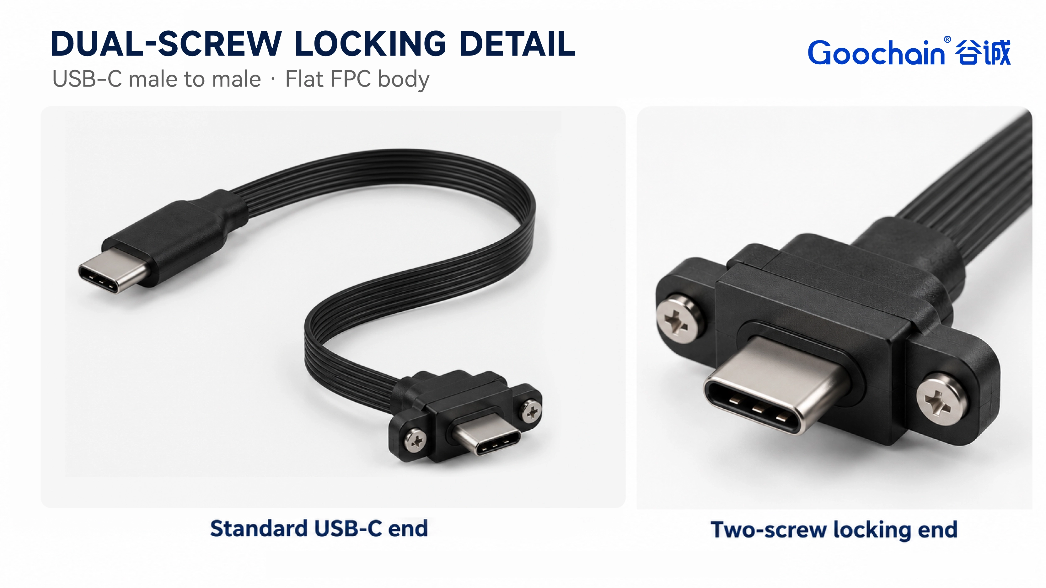
The locking hardware secures the connector, while the ribbon still needs a suitable route and support. Define the usable space, obstacles and cable restraint so handling loads do not concentrate at the transition between the FPC and connector housing.
The finished length should follow the installed path rather than only the straight-line distance between ports. Include covers and nearby components in the layout review. If the cable moves during use, describe that motion separately from the flexibility needed to install it.
Mechanical retention does not establish the data rate, charging power or video capability. Define those functions for the selected cable and connected equipment, including any additional cable or interface that forms part of the connection.
Likewise, a screw-locking design does not establish a vibration or pull-test rating on its own. Any required claim needs an agreed test method and acceptance criteria for the finished assembly in its intended mounting arrangement.
For the broader relationship between connector selection, available routing space and required functions, read USB-C FPC Cable Selection for OEM Equipment.
As a locking USB-C cable manufacturer and OEM supplier, Goochain coordinates connector selection, locking-housing design, FPC geometry and cable restraint. Our factory supports sample development, assembly and inspection planning around the approved product specification.
The mating-interface drawing provides the reference for connector fit and locking dimensions. Samples can then be evaluated with the actual equipment, covers and cable supports. Agreed inspection points link the accepted sample to the dimensions and electrical functions checked during production.
No. The equipment needs matching threaded fixing points and compatible connector clearance. A standard USB-C opening alone does not provide a screw-locking interface.
Yes. Goochain can configure retention at one end or both ends. The opposite connector type, gender and orientation are specified for the selected assembly.
No. Identify the required locking interface or provide a dimensioned mating drawing. Screw position, thread specification and engagement length must be matched to the equipment.
No. Panel mounting fixes a receptacle to the enclosure. Screw locking retains the mating plug at a compatible interface. A panel-mounted socket does not automatically provide a locking connection for the plug.
A vibration rating requires an agreed test method and acceptance criteria for the complete assembly and installation. The presence of screws alone is not a test result.
No. Locking geometry does not define electrical capability. Data rate, power and any video function must be specified and evaluated for the selected cable and connected equipment.
Keep required fields minimal. Attach drawings/photos for accurate quoting.
Tip: A simple installation photo often saves 2–3 rounds of questions.
Quotation 1–2 days; development 15–20 days; mass production 20–25 days (project dependent).
Yes. Reference sample + requirements helps confirm drawings and test plan.
Depends on materials and complexity. We support prototypes and scalable mass production.


 English
 简体中文
简体中文  Deutsche
  Italian
  français
  Español
  Nederlands
  日本語
日本語  한국어
한국어  عربى
عربى  português
  Türk
Türk