

A 12-contact Pogo Pin connection can follow a defined cable route or sit directly on a board. Start with the positions of the equipment interfaces, then choose the assembly format that fits the installation and supply scope.
Goochain’s black 500 mm USB-A male to 12-pin Pogo Pin cable follows a routed connection. The USB-A female to 12-pin male direct-solder PCB connector fixes the interfaces in the board layout. Use the mating drawing and pin map for each configuration.
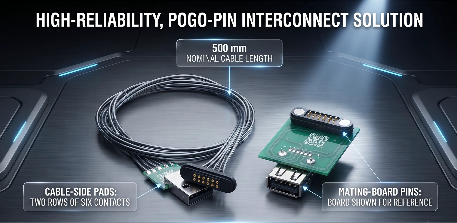
| Design item | 500 mm cable | Direct-solder PCB connector |
|---|---|---|
| USB-A interface | USB 3.0 Type-A male plug | USB Type-A female receptacle |
| Device interface | 12-contact Pogo Pin mating face | 12-pin male Pogo Pin end |
| Mechanical reference | Cable length datum, exit and routing space | Board outline, footprint and installed height |
| Quotation input | Wiring map, mating drawing and cable configuration | Solder termination, board layout and supplied parts |
Use the Custom Spring Loaded Pogo Pin Cables category to compare available routing and connector options when the assembly requires a cable.
For the cable, specify the two ends of the 500 mm measurement and the routing position during assembly. Check where the cable exits each housing and where it needs space to bend.
For the board connection, release the footprint alongside the connector drawing. Identify the board reference, solder location, approach direction and clearance to the enclosure. The quotation should state whether the order includes a PCB and what assembly work is included.
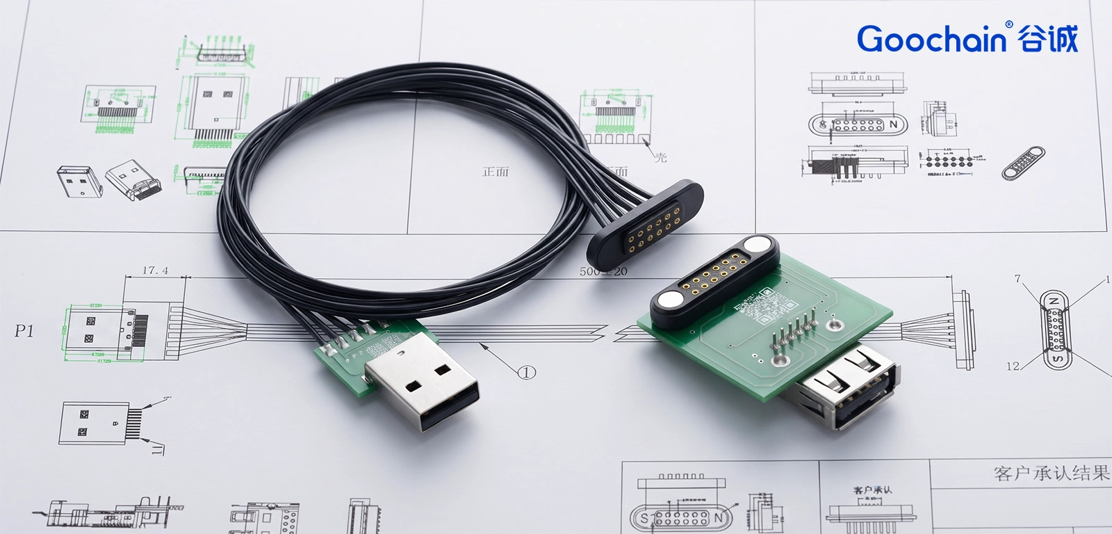
Use a numbered face view for each design. Confirm the matching connector, contact pitch, orientation, fit and contact assignments as one set. A shared contact count alone gives too little information to establish a mating combination.
The USB 3.0 designation on the cable describes its Type-A plug. Define the intended power and data operation for the connected equipment, then verify that operation on the actual sample configuration.
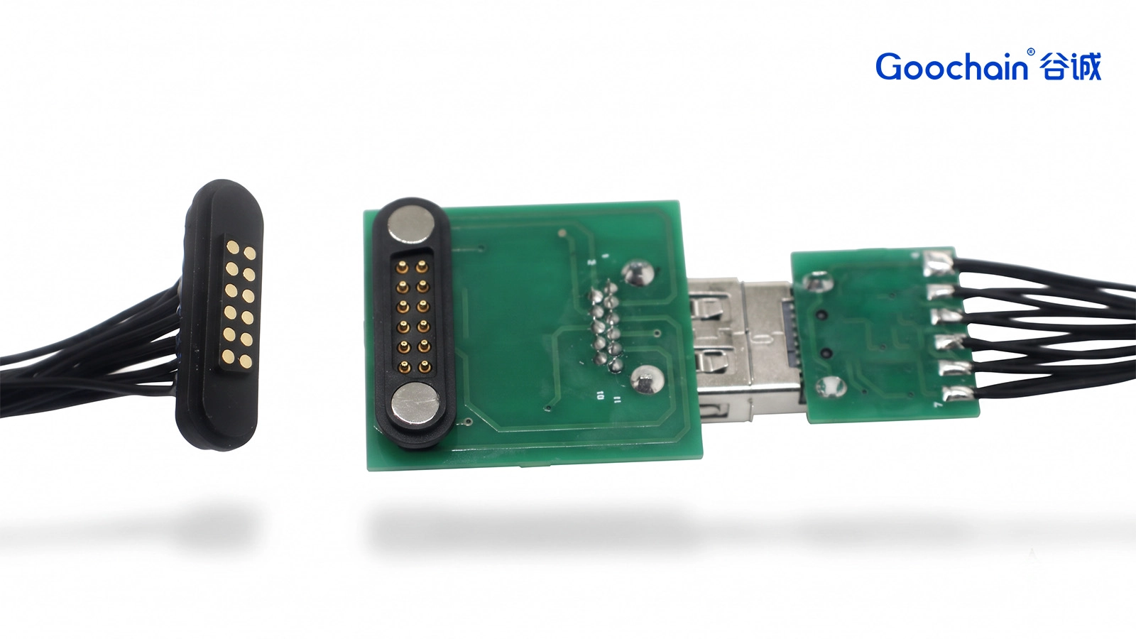
Send the routing drawing or PCB layout, both mating faces, the contact map, electrical requirements, quantity and the intended supplied parts. Use the same drawing revision for the quotation and the sample review.
Choose a cable when the two ends need a defined route and the available space can accommodate the cable exit and bend.
Confirm the footprint, board outline, installed height, mating direction and solder termination drawing.
Use both mating drawings, contact geometry, viewing direction and the pin map to establish the actual pairing.
State the intended power and data functions, the connected equipment and the checks required for the final assembly.


 English
 简体中文
 Deutsche
 Italian
 français
 Español
 Nederlands
 日本語
 한국어
 عربى
 português
 Türk


