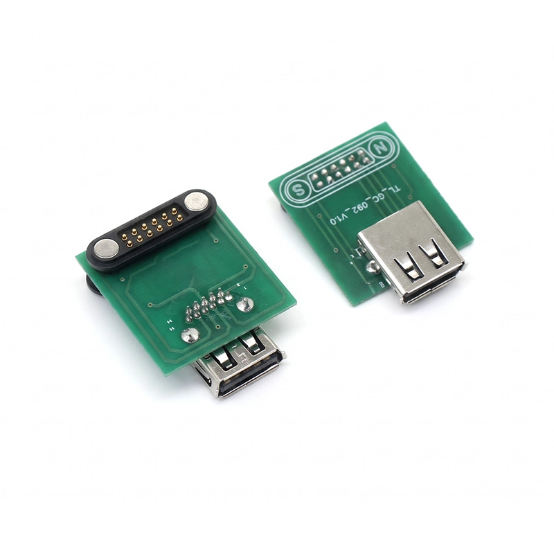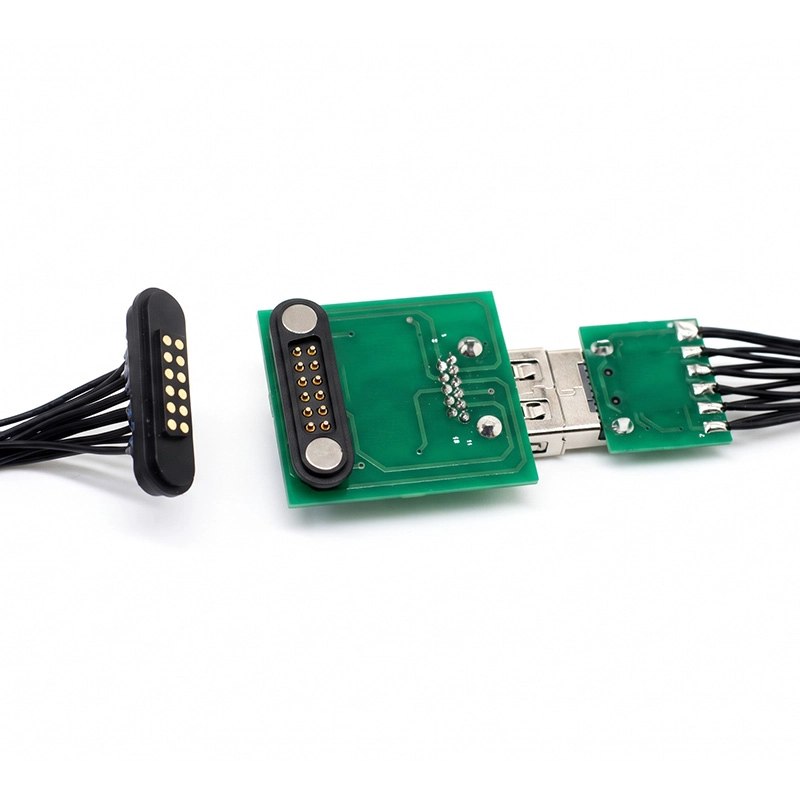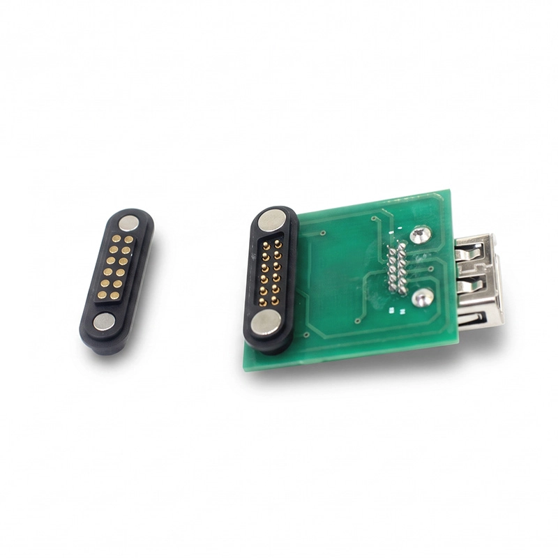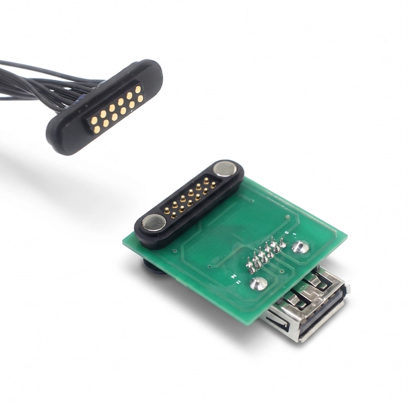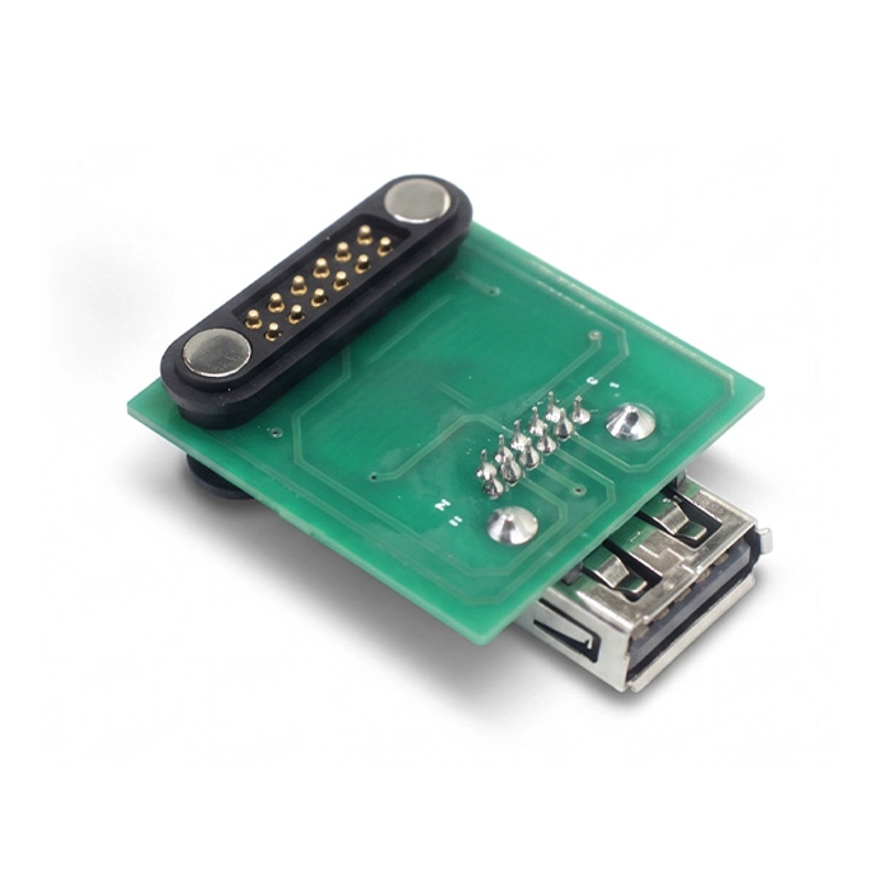


USB Type-A receptacle and 12-pin male Pogo Pin interface for direct PCB soldering. PCB and assembly scope are confirmed in the quotation.
This direct-solder PCB connector pairs a USB Type-A receptacle with a 12-pin male Pogo Pin interface. Use the board and enclosure drawings to check access to the USB-A opening and clearance for the 12-pin mating end.
This direct-solder PCB connector pairs a USB Type-A receptacle with a 12-pin male Pogo Pin interface. Use the board and enclosure drawings to check access to the USB-A opening and clearance for the 12-pin mating end.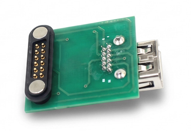
Locate the receptacle from the enclosure opening. With the board in its installed position, check the direction of engagement and the space needed to mate the 12-pin end.
For other board-side interfaces, see Goochain’s Spring Loaded Pin Connector range.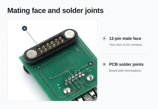
Confirm the solder footprint against the connector drawing. On the 12-contact face view, mark pin 1 and the viewing side so the PCB layout and continuity check use the same numbering.
List the connector parts, any PCB and the assembly work you need. If you supply the board, send its drawing so the quotation can reference your layout.
Agree which solder joints and contact paths to check on the sample. Goochain’s Factory & Quality page outlines the inspection process.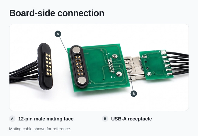
Send Goochain your board outline, solder footprint, mating drawing and pin map. List the parts or assembly work you need and the target quantity.
Keep required fields minimal. Attach drawings/photos for accurate quoting.
Tip: A simple installation photo often saves 2–3 rounds of questions.
Quotation 1–2 days; development 15–20 days; mass production 20–25 days (project dependent).
Yes. Reference sample + requirements helps confirm drawings and test plan.
Depends on materials and complexity. We support prototypes and scalable mass production.


 English
 简体中文
 Deutsche
 Italian
 français
 Español
 Nederlands
 日本語
 한국어
 عربى
 português
 Türk