

A dual-interface connector is ready for engineering review when the two mating views, installed geometry and electrical map describe the same configuration. Set those references before reviewing a prototype or requesting a production quotation.
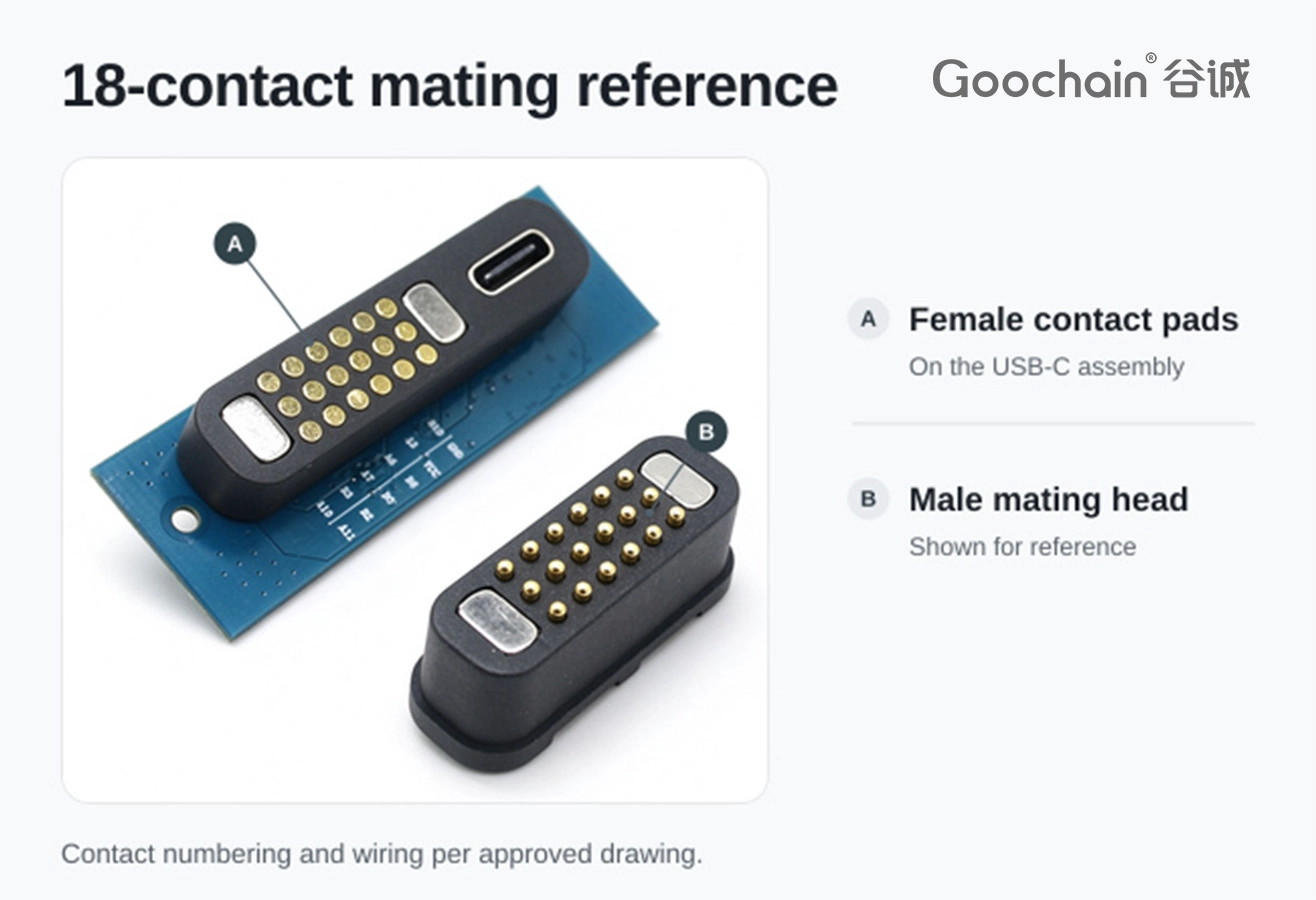
The Goochain 18-pin female Pogo Pin and USB-C receptacle assembly combines an 18-pin female Pogo Pin interface with a USB Type-C receptacle. The drawing package should define both sides and the internal connection together.

Show the 18-contact face from a defined viewing direction. Give the numbering start point, contact positions, outline and expected mating direction. Show the USB-C receptacle opening and its orientation relative to the equipment housing.
For related interface configurations, consult the Spring Loaded Pin Connector category while preparing the mechanical specification.
| Drawing item | What to show |
|---|---|
| 18-contact side | Mating face, numbered contacts, alignment reference and engagement direction |
| USB-C side | Receptacle orientation, opening position and clearance for the mating plug |
| Mounting | Envelope, fixed points, access and clearance around the assembly |
| Internal termination | Connection geometry and the parts included in the supplied configuration |
| Electrical map | Contact assignments, intended power and data functions, and sample checks |
Record each circuit function beside its contact number. Define the intended power and data requirements and the equipment on either side. Review internal termination and circuit behaviour on the actual configuration before publishing any electrical rating.
When the mating direction or mounting reference changes, update the face view and electrical map together. Procurement can then use the drawing revision to confirm the quoted assembly and the parts included in the order.
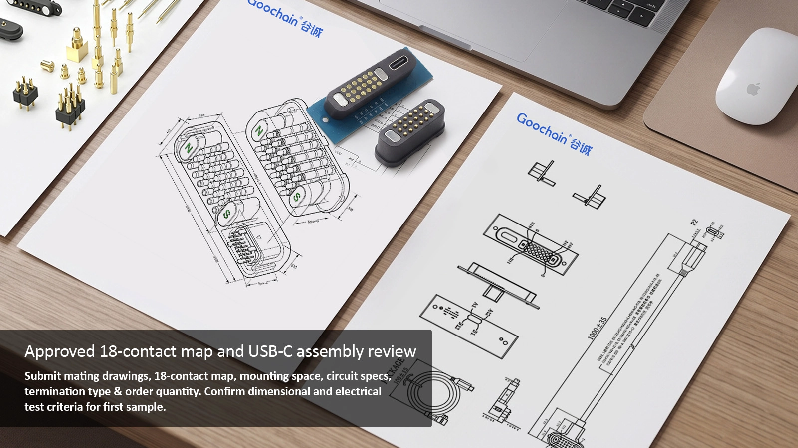
Send both mating drawings, the 18-contact map, the available installation space, the circuit requirements, the expected termination and order quantity. Agree which dimensional and electrical checks the first sample needs to pass.
Show the 18-contact female face and the USB-C receptacle face with a defined viewing direction and installation reference.
Use a consistent face view and reference position. Cross-reference each contact with its circuit assignment and mating contact.
The circuit, contact assignments and validated assembly configuration establish the functions available to the target device.
Check envelope size, connector orientation, engagement clearance, fixed points and access for both mating parts.


 English
 简体中文
 Deutsche
 Italian
 français
 Español
 Nederlands
 日本語
 한국어
 عربى
 português
 Türk


