

At USB 10Gbps, a Pogo Pin connector cannot be evaluated only by checking whether each contact conducts electricity. The complete channel includes the USB Type-C connector, cable or FPC, terminations, spring-loaded contacts, mating pads, device PCB, host, device and any test fixture.
Every transition can introduce loss, reflection, skew or crosstalk. Reliable performance comes from managing these effects across the entire path and then validating the assembled system.
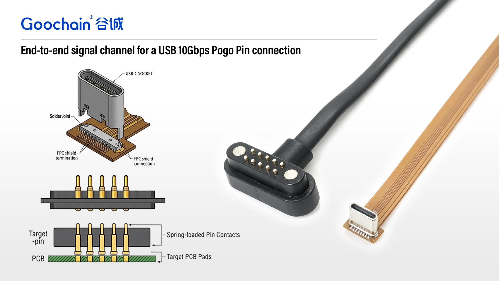
USB SuperSpeed signals travel as differential pairs. Pair geometry should remain consistent through the cable or FPC and across connector transitions. Large changes in spacing, reference, path length or routing direction can disturb the channel.
The design should minimize unnecessary stubs and abrupt changes. Pair members should be treated together from the USB connector through the Pogo Pin interface and into the device PCB.
Cable construction, FPC layer stack, conductor geometry, dielectric material, ground reference and connector layout influence differential impedance. A controlled cable does not guarantee a controlled connector transition; the termination and mating pad must also be reviewed.
Where the geometry must change, the transition should be short and deliberate. Simulation, measurement or comparison with a validated reference design may be used according to project requirements.
High-speed current requires a continuous return path. Ground contacts and shields should be positioned and connected to support the data pairs rather than added as unrelated pins.
A break in the reference plane or a long indirect ground path can increase radiation, susceptibility and signal discontinuity. The Pogo Pin layout and the device PCB land pattern should therefore be developed together.
One advantage of a multi-pin Pogo Pin connector is the ability to carry power, USB data and auxiliary signals through one interface. The same density can create coupling if high-speed pairs are placed too close to switching power, clocks or other noisy signals.
Pin assignment should consider signal groups, ground separation, current paths and simultaneous operating conditions. Testing should include realistic charging and data operation when both functions will be used together.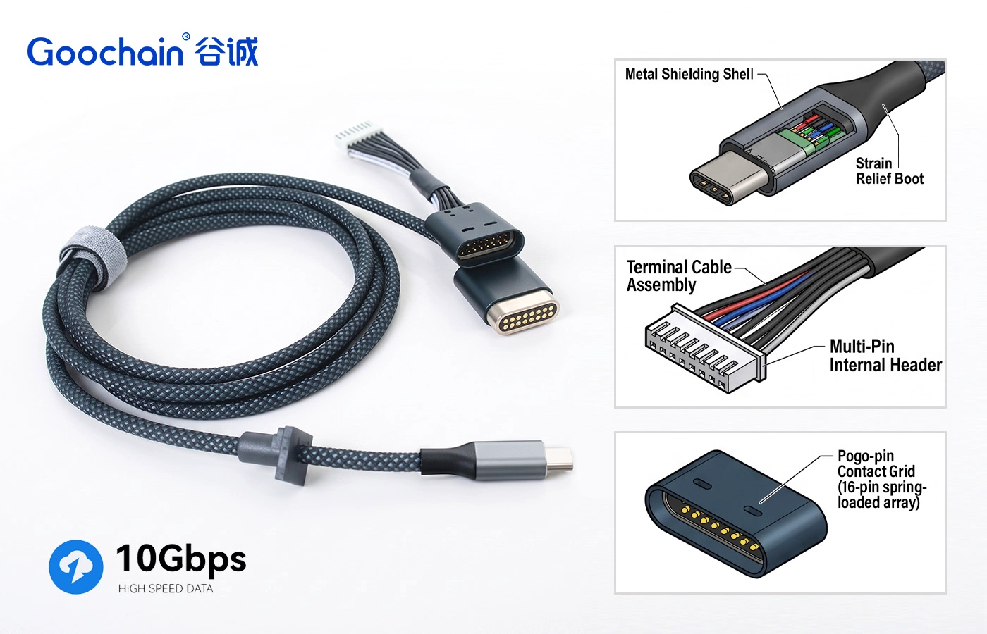
Longer channels generally leave less margin for loss and discontinuity. Cable conductor construction, shielding, bend, overmold transition and termination quality all matter.
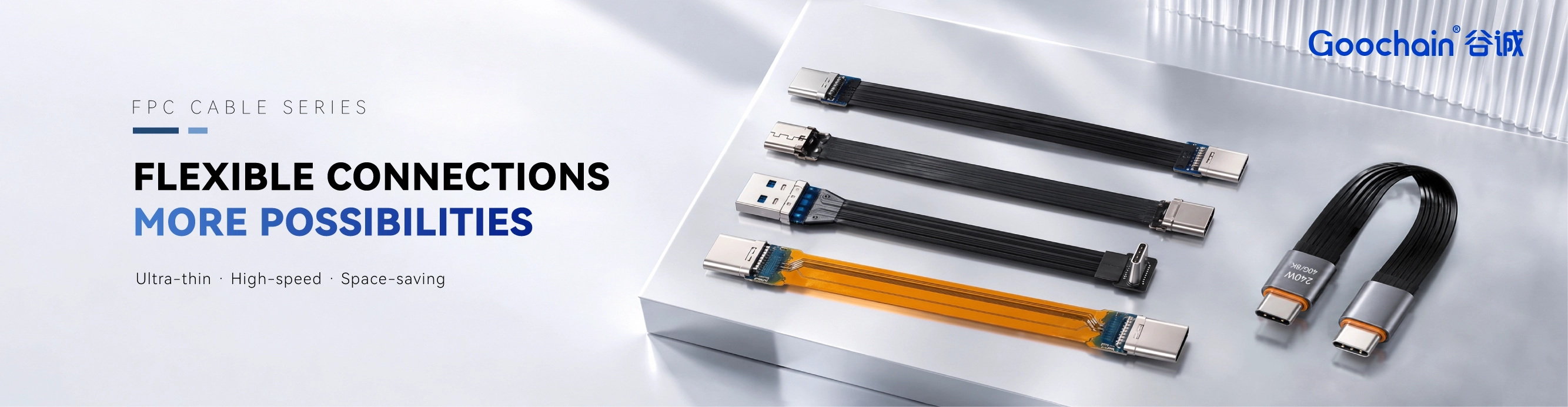
For FPC, the layer stack, copper geometry, coverlay, stiffener and bend zone affect the result. Compare round cable and FPC options based on the actual mechanical path rather than assuming one structure is always electrically superior.
The electrical path changes if the contacts do not engage at the designed position. Working stroke, contact force, magnet alignment, housing tolerance, coplanarity, pad size and surface condition influence stability.
The connector should tolerate normal docking variation while keeping the contacts within the validated range. Mechanical testing and electrical testing should use the same approved mating condition.
The transition from USB Type-C into the cable or FPC and the transition from the Pogo Pin mating pad into the device PCB are common places for discontinuity. Connector breakouts, vias, pads, plane changes and component placement should be reviewed as part of the channel.
When Goochain supplies only the cable assembly, cooperation with the customer's PCB team is important. A well-designed cable cannot correct a poorly routed device-side transition.
Shielding performance depends on how the shield is terminated and connected to the equipment. Gaps, long drain paths or floating metal parts may reduce effectiveness. The enclosure, connector housing and cable shield should be considered together.
For magnetic connectors, the mechanical and magnetic components must also be assessed so that they do not compromise the intended grounding or high-speed geometry.
Depending on the project, validation may include:
The test plan should identify the host, device, fixture, cable length, product revision and acceptance criteria. See Goochain's tested USB-C to magnetic Pogo Pin cable for a current product direction. When a formal USB 10Gbps Pogo Pin cable test report is available, link the exact report to the exact tested configuration.
A prototype that passes once is not enough for mass production. Critical materials, cable preparation, FPC revision, termination process, connector components, molding dimensions and inspection limits must be controlled.
Useful production controls may include approved samples, revision-controlled drawings, conductor and shield preparation standards, fixture-based electrical testing, dimensional checks, contact inspection and defined change-control rules.
Signal integrity in a USB 10Gbps Pogo Pin connection is the result of coordinated electrical and mechanical design. Differential routing, impedance transitions, return paths, crosstalk, cable or FPC structure, contact stability and PCB integration must be managed as one channel.
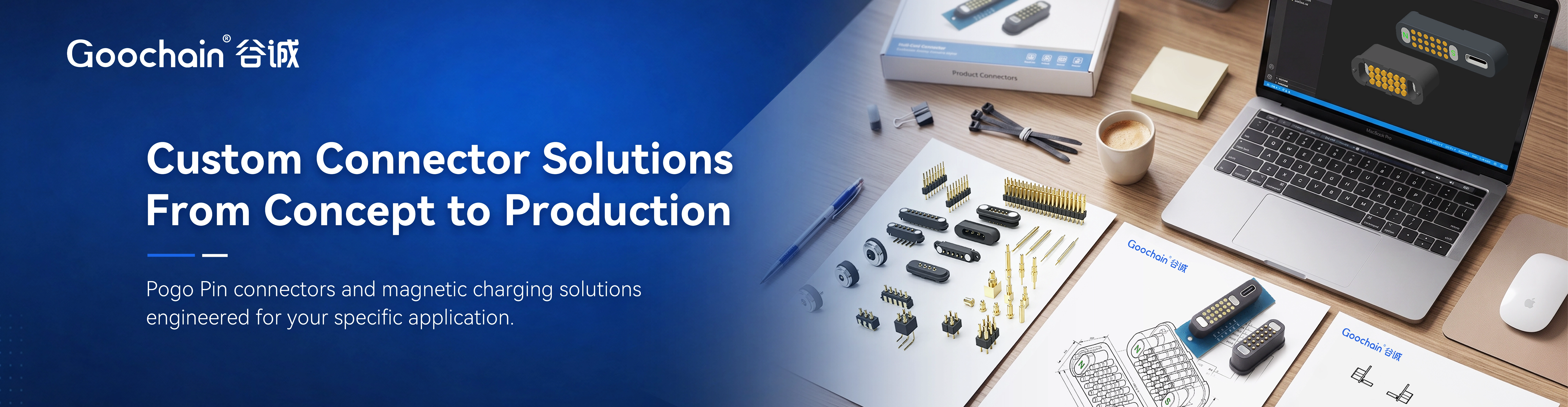
For a custom project, review Goochain's high-speed Pogo Pin connector solutions and provide the device drawing, pinout and system requirements for engineering evaluation.


 English
 简体中文
简体中文  Deutsche
  Italian
  français
  Español
  Nederlands
  日本語
日本語  한국어
한국어  عربى
عربى  português
  Türk
Türk 

