

A 90-degree USB-C cable is not fully specified until its exit direction and connector clearance are defined. The same problem becomes more important with two angled ends or a 180-degree return, because a cable that looks correct in a product photo can point the wrong way when it is installed in the actual equipment.
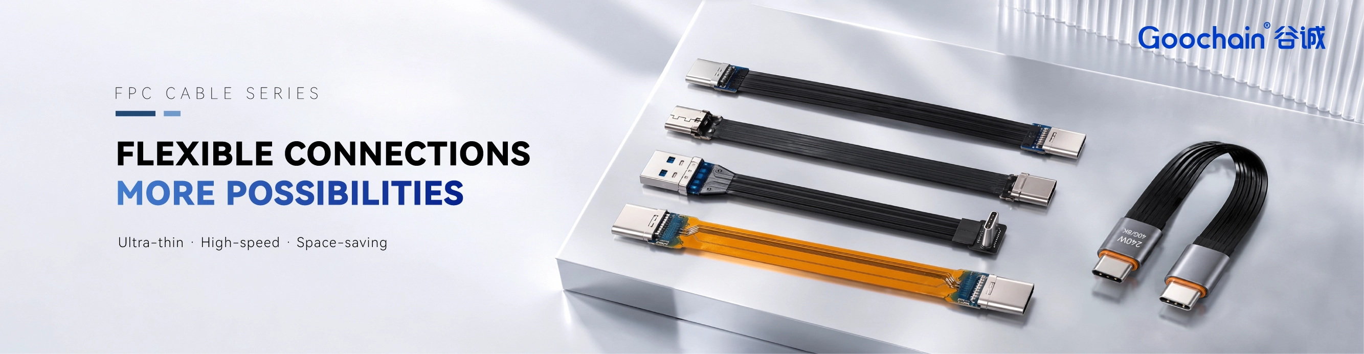
Goochain develops custom FPC ribbon cable assemblies for compact OEM equipment. For angled USB-C projects, the most reliable starting point is a drawing that fixes the viewing direction, labels both ends and shows the available space around each port. This turns a verbal description such as “left angle” or “U shape” into dimensions that engineering, purchasing and production can all verify.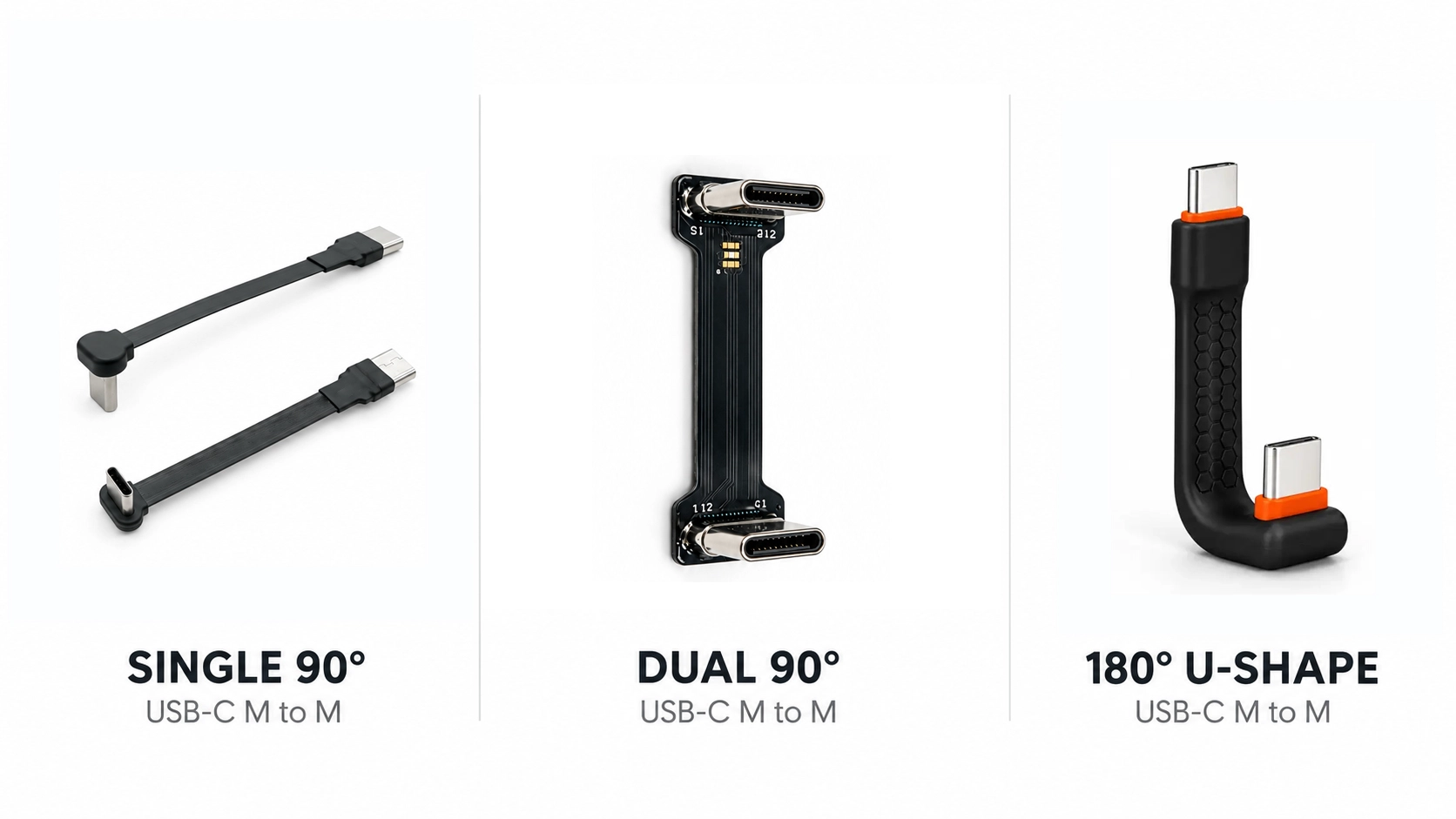
Terms such as left angle, right angle, up angle and down angle are relative. A supplier may describe the connector while looking into the plug, while the customer may be looking directly at the device receptacle. A photograph taken from the rear of the equipment can reverse the apparent direction again. Without a stated viewpoint, both parties can use the same word and still mean opposite layouts.
USB-C is reversible electrically at the user interface, but rotating the plug does not necessarily solve a mechanical orientation mistake. The molded housing, FPC exit and nearby equipment features may occupy different spaces after rotation. If the connector body carries a logo, retention feature, asymmetrical overmold or fixed FPC transition, the two inserted orientations can produce different installed results.
Start with a front view looking directly at the device port. Mark the top of the equipment and add an arrow showing the viewing direction. Name the connectors A and B, even if both are USB-C male plugs. Then draw an exit arrow beside each connector to show where the FPC or cable body must travel after the plug is fully seated.
This reference is more useful than asking the factory to copy a catalog photograph. The drawing remains clear if the product is later viewed from another angle, and it gives incoming inspection a stable way to confirm that the manufactured connector direction matches the approved sample.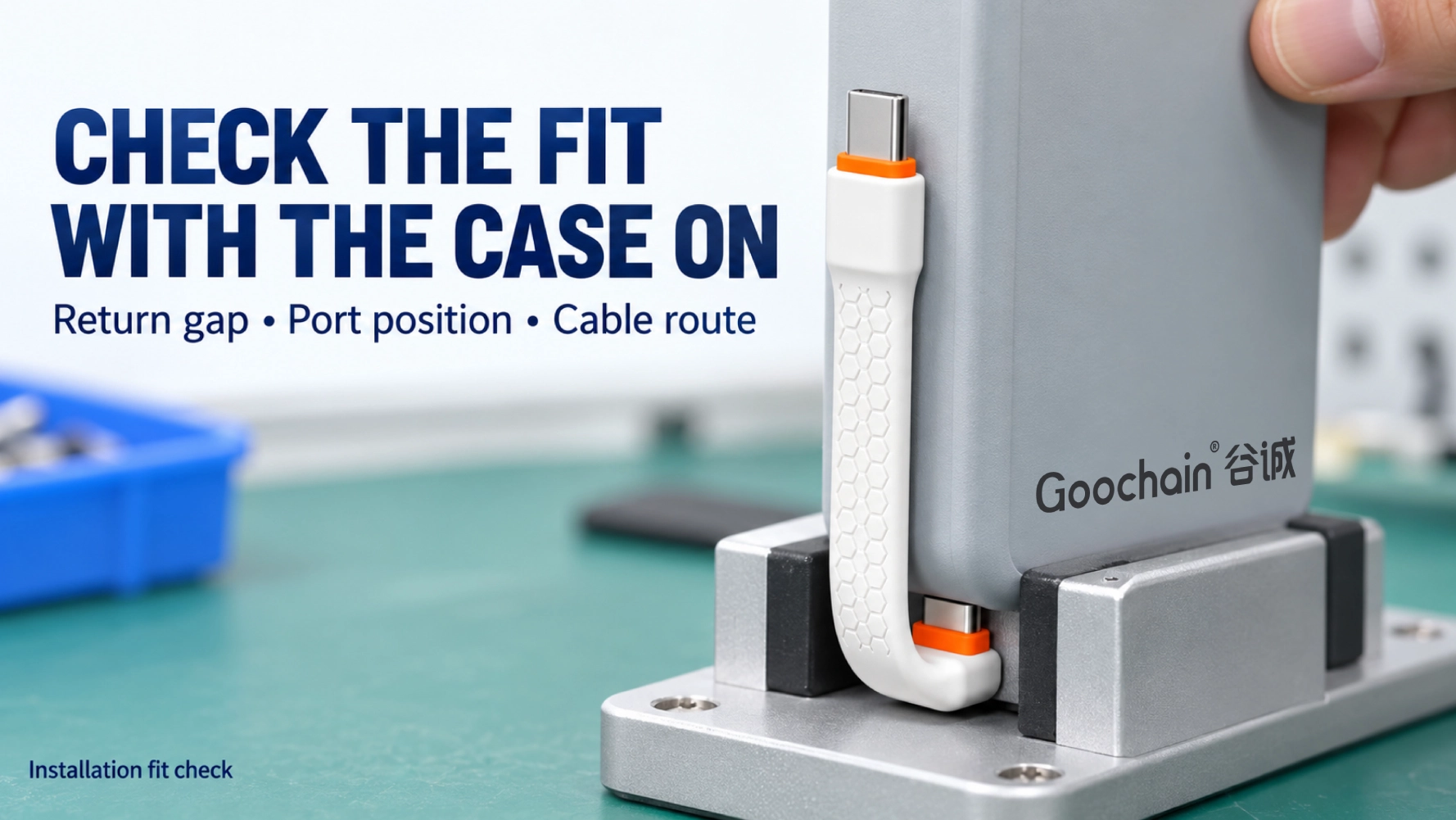
These three arrangements solve different installation problems. A single 90-degree end redirects the route near one port. A dual-angle cable controls the exit at two separate ports. A U-shaped end returns the connection around a device edge. Treating them as interchangeable can lead to the wrong housing, the wrong end relationship or insufficient case clearance.
| Arrangement | What it controls | Critical dimensions | Common mistake |
|---|---|---|---|
| One 90-degree end | The route immediately after one port | Housing height, side projection and FPC transition | Naming the direction without fixing the view |
| Two 90-degree ends | The exits at two separate USB-C ports | A/B directions, port spacing, route length and end relationship | Confirming one connector but leaving the other undefined |
| 180-degree U-shaped end | The return around a device or case edge | Return gap, case thickness, port recess and seating depth | Choosing by appearance without checking the installed gap |
A dual-angle cable needs more than two 90-degree callouts. The drawing must show whether the two exits point in the same direction, in opposite directions or onto different planes. It should also locate the measurement points used for cable length. Measuring from the metal plug tip, housing edge or FPC transition produces different values, especially on a short assembly.
The Dual Right Angle USB-C Male to Male FPC Cable is a useful reference for equipment that has limited exit clearance at both ports. It is a male-to-male arrangement with a separate 90-degree connector at each end; it is not the same as a single connector that returns 180 degrees around one edge.
Check the complete mated envelope rather than only the metal shell. A raised lip around the receptacle may prevent the housing from seating fully. A neighboring port may be accessible when empty but become blocked after its own cable is connected. The drawing should therefore include adjacent plugs, covers, brackets and fasteners that remain present in service.
A U-shaped connector routes the cable back along or behind the device instead of projecting straight outward. The key dimension is the clear space inside the return. That gap must accommodate the equipment edge while allowing the USB-C plug to reach its fully seated position.
For an 180 Degree U-Shaped USB-C FPC Cable, provide a side section showing the case thickness, port recess, connector seating depth and required return gap. Include any protective cover, decorative trim or bumper that remains fitted during use. A sample that fits a bare device may no longer seat after the final enclosure or protective case is installed.
The drawing should also show where the FPC leaves the U-shaped housing and the direction it follows afterward. Do not use a sharp fold in a straight FPC as a substitute for a designed return. The connector transition and bend region must be developed for the intended geometry, supported during assembly and evaluated in the finished installation.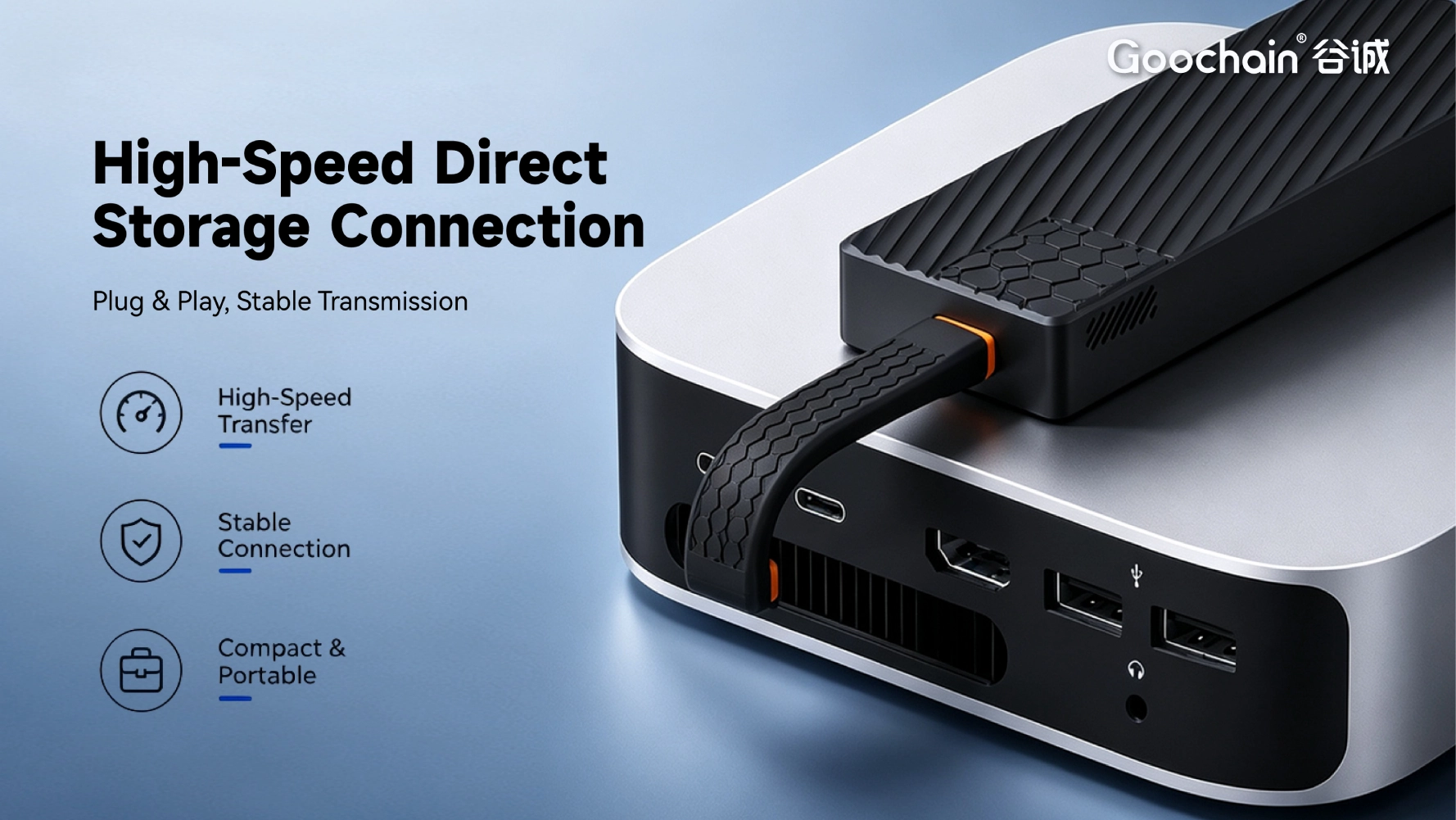
A cable may fit in its final position but still be difficult to assemble. Define which connector is inserted first, how the second end is reached and when the enclosure cover is installed. On a short dual-angle assembly, the installer may need temporary movement that is impossible after one connector or bracket has been fixed.
Mark the permitted FPC area and any keep-out zones created by screw bosses, board edges, heat sources or moving parts. Add local support where insertion, removal or vibration could load the connector transition. The thin appearance of FPC does not remove the need for strain management at mechanically loaded interfaces.
If the cable moves only during installation, describe it as a static route after assembly. If it must flex repeatedly in service, state the motion, bend region, expected cycle requirement and restraint method separately. A cable that can be bent into place is not automatically designed for continuous dynamic flexing.
A 90-degree or 180-degree shape does not determine data rate, charging power or video capability. These functions depend on the complete electrical design and the connected system. State data, power and video requirements as separate items, together with the host, peripheral and any downstream cable used in the final connection.
When the connector direction, FPC outline or overall length changes, treat the result as a specific assembly that needs its own review. Performance from a short straight cable should not be assumed for a longer angled version. The sample evaluation should confirm mechanical fit first and then verify the required functions with the intended devices and operating arrangement.
A clear quotation package reduces repeated questions and lets different suppliers price the same scope. For a custom angled USB-C cable, provide the following information in one marked drawing or specification:
Goochain can review the connector orientation, FPC geometry, molded housing option and installation constraints as one assembly, then prepare samples for fit and functional evaluation. The approved drawing, identified sample and agreed inspection points should remain linked through production so the repeat order is controlled by measurable requirements rather than a general phrase such as “right-angle USB-C cable.”
No. The angle changes the exit direction, but the connector housing still has height, width and side projection. Compare the complete mated connector envelope with the actual space around the port.
A photo helps explain the application, but it can reverse the apparent direction or hide critical dimensions. A fixed-view drawing with A/B labels, exit arrows and clearances provides a better manufacturing and inspection reference.
No. A dual right-angle cable has a separate 90-degree connector at each end. A U-shaped cable uses a 180-degree return at one specified end to route the cable around an equipment edge.
No. Reversibility helps with mating, but the angled housing and FPC exit still occupy physical space. Rotating the plug can move those parts into a cover, bracket or neighboring connector.
The angle alone does not assign a data rate or power level. The selected cable configuration must be designed and evaluated for its required data, charging and video functions in the intended connected system.


 English
 简体中文
简体中文  Deutsche
  Italian
  français
  Español
  Nederlands
  日本語
日本語  한국어
한국어  عربى
عربى  português
  Türk
Türk 

