

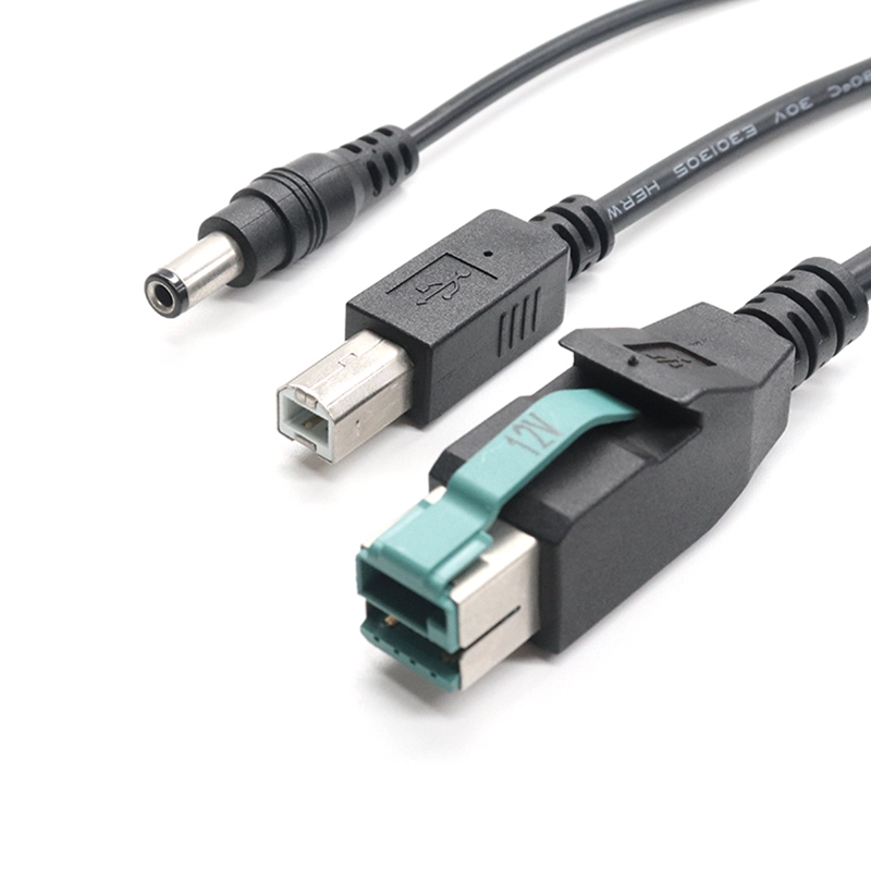
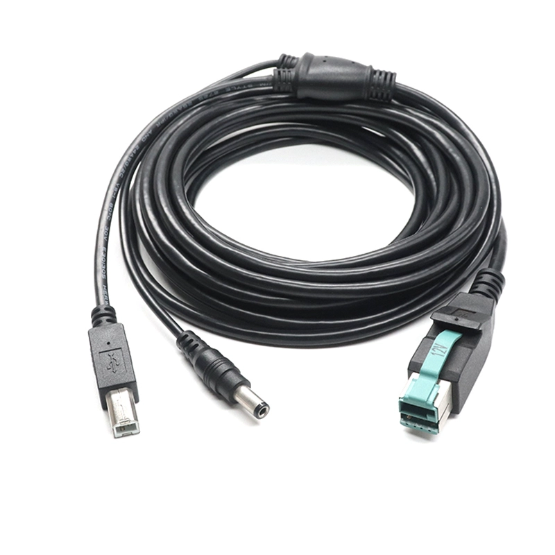
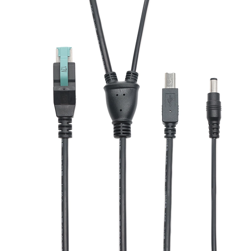
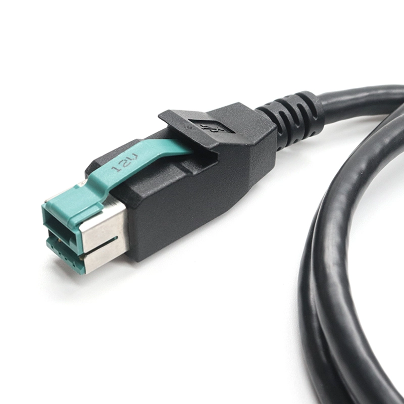
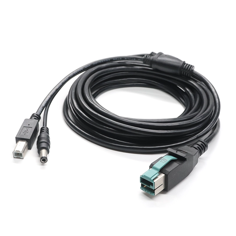
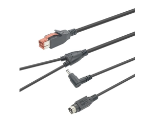
A USB-B data connection and a matched DC barrel power branch for POS equipment with separate device-side sockets.
When a POS peripheral has a USB-B socket and a separate DC power jack, the power plug needs as much attention as the data connector. Goochain builds this POWEREDUSB Y cable with a USB-B data branch and a DC barrel power branch, matched to the actual device sockets. The DC outer diameter, inner diameter, insertion length and polarity are recorded together, while the split position and branch lengths follow the rear-panel layout. Each powered USB assembly uses the selected host voltage and approved wiring. In the passive version, the DC branch carries the specified host auxiliary supply; a different output voltage requires a separately designed conversion circuit.
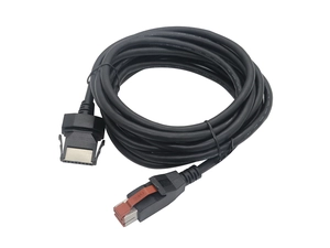
Goochain manufactures POWEREDUSB Y cable assemblies for POS peripherals with a USB Type-B data socket and a separate DC barrel power input. One POWEREDUSB male connector links to the host; the device end divides into a USB-B male data branch and a DC barrel male power branch.
The DC plug is selected for the actual equipment jack, including its outer diameter, inner diameter, insertion length and polarity. This configuration is part of our POWEREDUSB cable range, with connector selection and branch dimensions defined for each OEM project.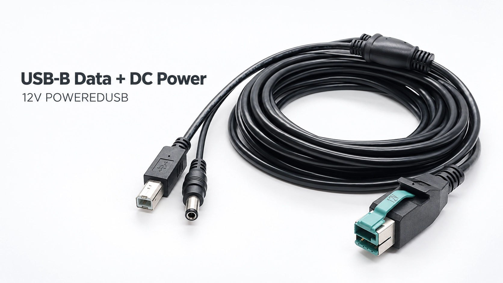
A barrel plug can look correct while leaving the center contact loose or stopping before it is fully seated. The mating-jack drawing or reference sample should define the dimensions below. Polarity is recorded separately on the wiring drawing.
| Detail to confirm | What the drawing should define |
|---|---|
| Outer diameter | The barrel size required by the equipment's DC jack. |
| Inner diameter | The fit between the plug's inner contact and the jack's center pin. |
| Insertion length | The engagement depth, including clearance around a recessed socket or enclosure opening. |
| Power polarity | The positive and negative assignments for the center and outer contacts. |
Center-positive and center-negative connections are specified individually. If the equipment instead uses a three-pin power inlet, our 24V POWEREDUSB USB-B 3-Pin Printer Y Cable is a different configuration that requires its own connector and pinout review.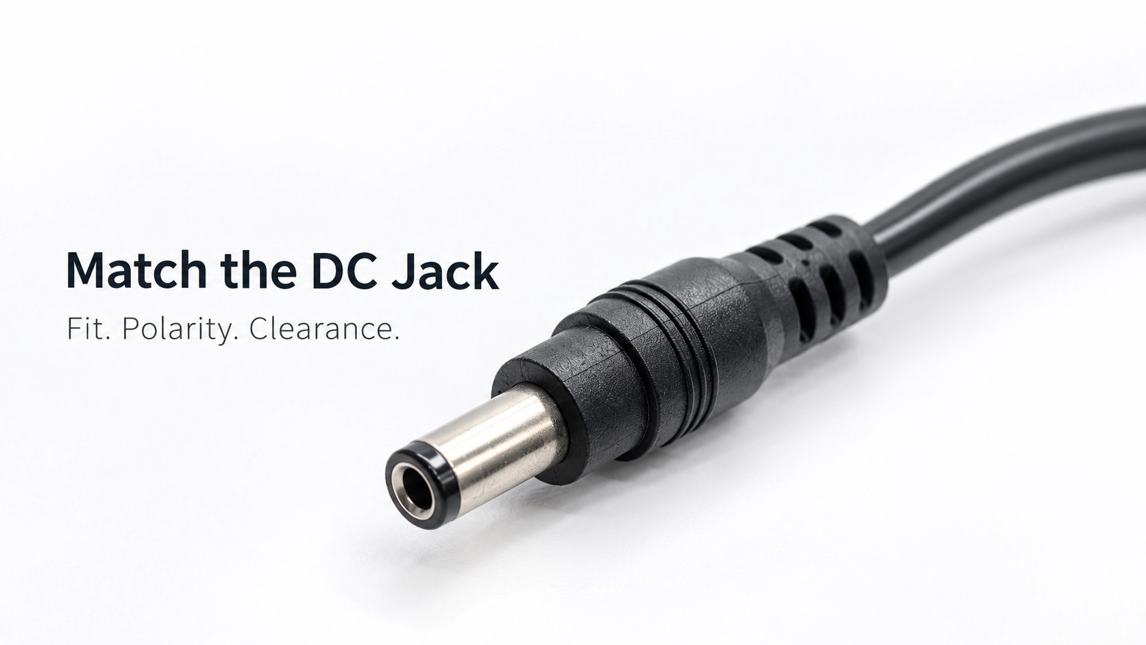
In the passive assembly, the host's specified auxiliary supply is routed to the DC power branch. The USB-B branch follows the approved USB wiring; the auxiliary 12V or 24V supply is not connected to standard USB-B VBUS. Host voltage keying, DC polarity and device power requirements must be reviewed together.
12V and 24V are separate cable configurations. This passive cable does not automatically select, regulate or convert the supply voltage. A different device voltage requires a separately designed conversion solution.
The USB-B socket and DC jack may sit at different depths or on different parts of the rear panel. Define each branch from a common reference point on the molded split to its connector reference face. The USB-B and DC branches can have different lengths so each plug reaches its socket without pulling sideways on the other.
For a recessed DC jack, check the plug housing as well as the metal barrel. A straight or angled exit must leave clearance for adjacent ports, the enclosure and normal unplugging. The main cable route, branch lengths and split position can then be reviewed as one assembly.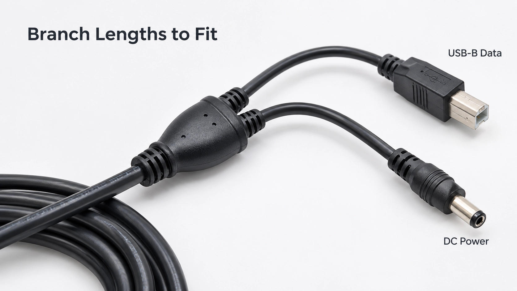
Goochain supports OEM manufacturing and ODM development of powered USB cable assemblies at its 5,000 m² facility in Dongguan. Custom work can include DC plug selection, branch lengths, cable construction, molded junctions, strain relief and identification.
Before production, the drawing and accepted sample define the supplied configuration. Inspection requirements can cover connector fit, continuity, DC polarity, branch dimensions and the required USB function, supported by our Factory & Quality process. Current capacity and USB performance are confirmed for the specified finished assembly.
For a project review, send the device model, DC jack drawing or sample, required voltage and current, polarity, branch layout and intended USB function. A clear photo showing both device sockets helps establish connector clearance and a practical first sample.
Keep required fields minimal. Attach drawings/photos for accurate quoting.
Tip: A simple installation photo often saves 2–3 rounds of questions.
Quotation 1–2 days; development 15–20 days; mass production 20–25 days (project dependent).
Yes. Reference sample + requirements helps confirm drawings and test plan.
Depends on materials and complexity. We support prototypes and scalable mass production.


 English
 简体中文
简体中文  Deutsche
  Italian
  français
  Español
  Nederlands
  日本語
日本語  한국어
한국어  عربى
عربى  português
  Türk
Türk 

