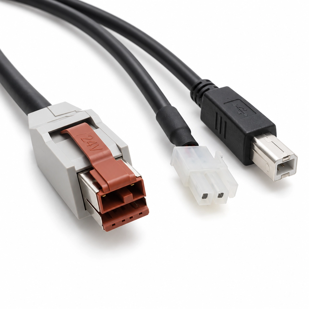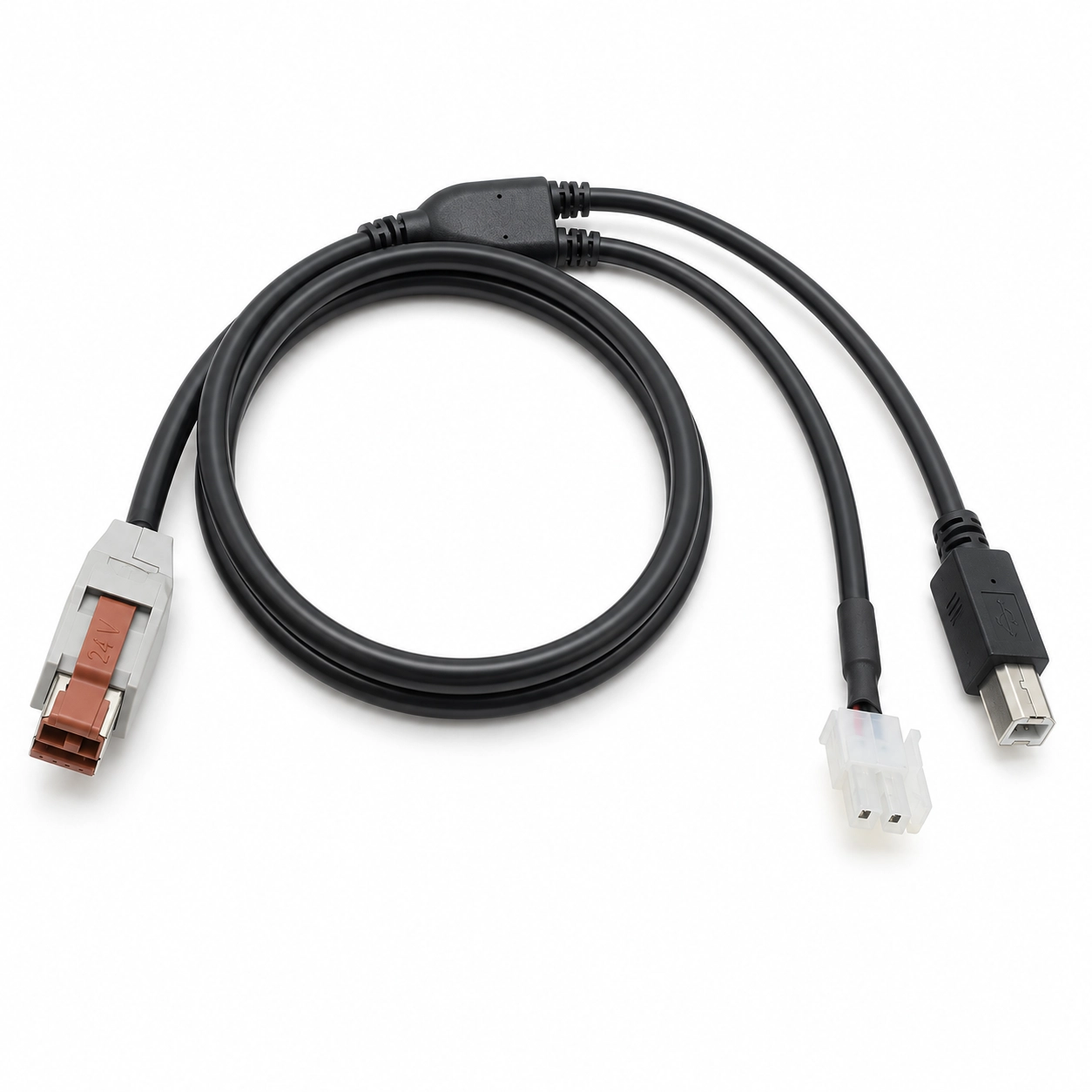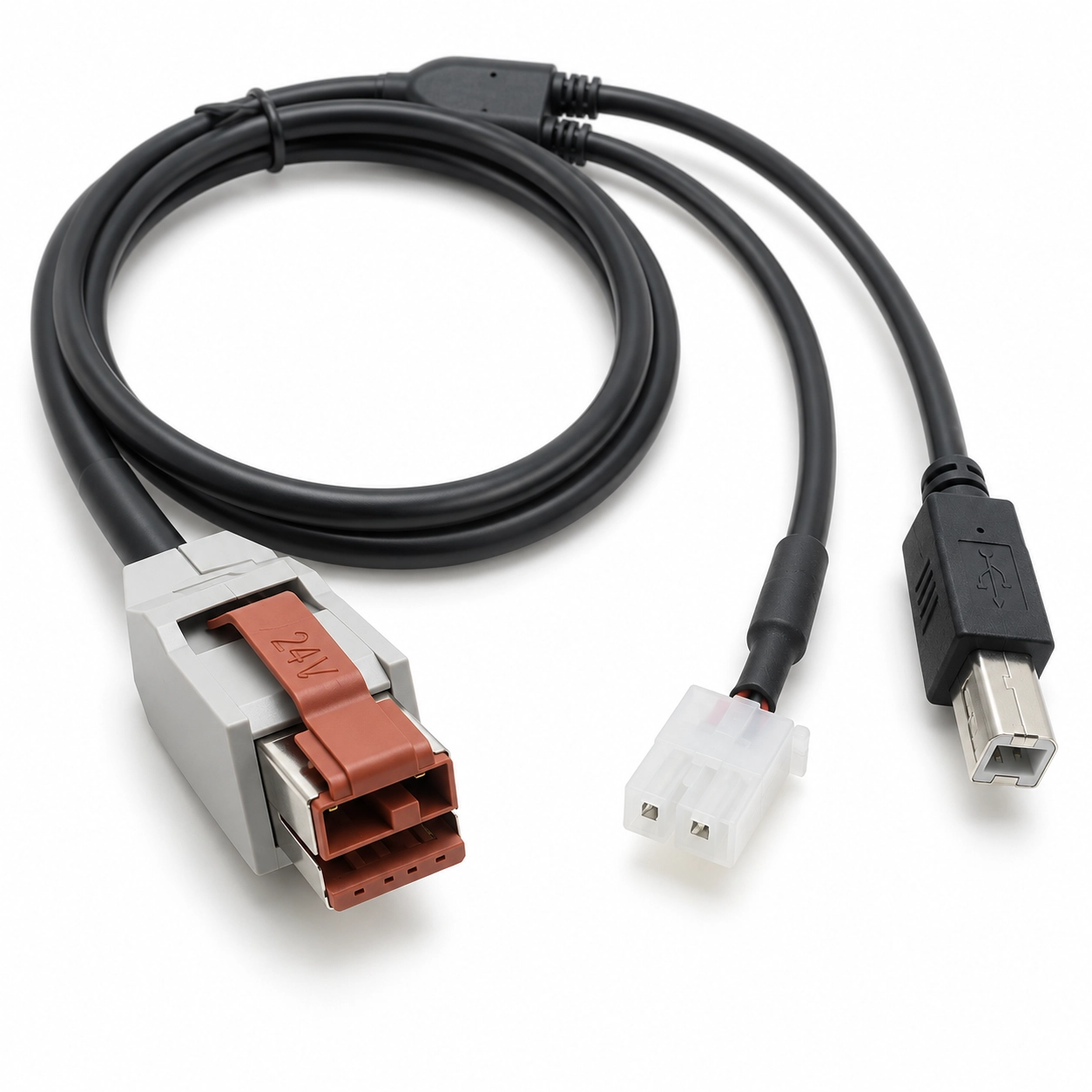



Separate USB data and 24V printer power into two branches matched to the spacing and connectors on the rear panel.
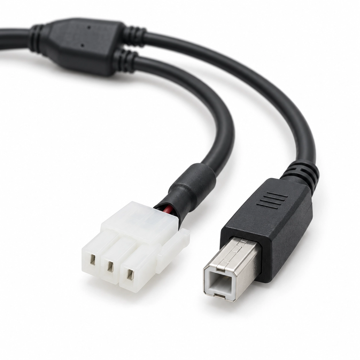
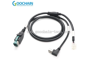
Some POS printers place the USB-B data socket and the power inlet several centimeters apart, so a single combined printer-end connector is not the right solution. This Goochain 24V POWEREDUSB Y cable splits near the printer into a USB-B branch for communication and a separate 3-pin branch for the specified 24V power connection. The useful dimensions are the branch lengths and the split position, not just the overall cable length. Goochain develops those dimensions around the rear-panel layout so each plug can be inserted, removed and serviced without one branch pulling sideways on the other.
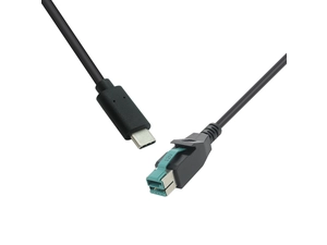
This 24V PoweredUSB Y cable is designed for printer and POS equipment layouts where USB communication and 24V power enter the device through two separate sockets. A 24V-keyed PoweredUSB connector links to the host side, while the printer side divides into a USB Type-B male branch and a separate 3-pin power branch.
The important part of this cable is not simply the Y shape. The location of the split, the free length of each branch and the exact 3-pin connector all need to match the rear-panel layout of the equipment. When these dimensions are defined correctly, both connectors can be plugged and removed without one branch pulling against the other.
Goochain develops this configuration as part of its custom PoweredUSB cable solutions for POS terminals, printers and commercial equipment. Connector matching, branch lengths, molded junctions and cable exits can be reviewed against the customer's drawing or equipment sample before production.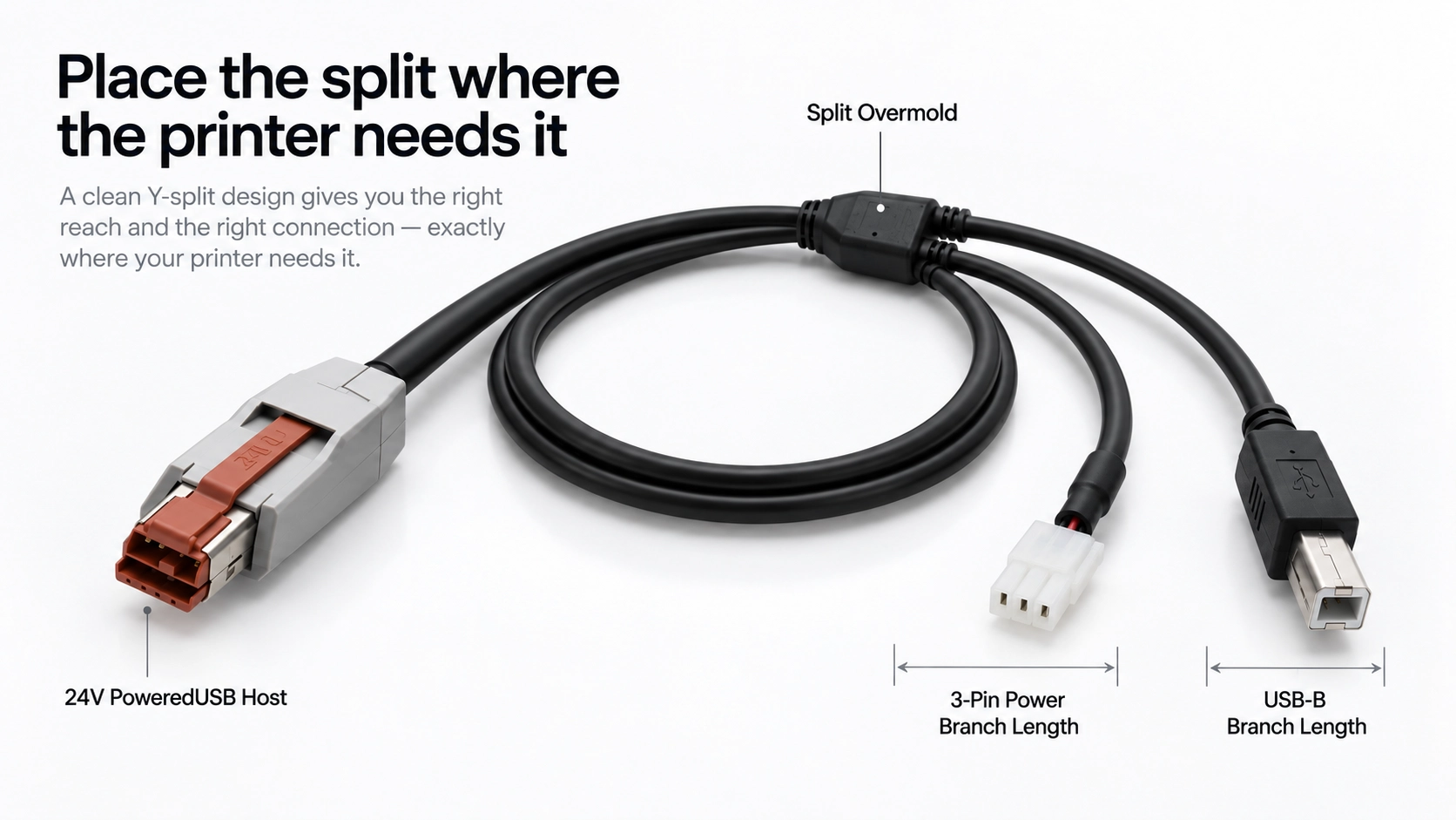
Some printer installations use one socket for USB communication and another socket for external power. In that layout, a single combined device-end connector is not suitable. The cable must reach both interfaces independently.
This PU07 configuration separates those functions after the molded junction. The USB-B branch connects to the printer's USB interface, while the 3-pin branch carries the specified 24V supply to the matching power socket.
This allows the host side to remain a single PoweredUSB connection while the printer side follows the actual socket layout of the equipment.
| Product Type | PoweredUSB Y cable assembly |
| Host Connector | 24V-keyed PoweredUSB |
| Data Branch | USB Type-B male |
| Power Branch | 3-pin printer power connector; exact connector series confirmed by drawing or mating sample |
| Supply Function | Host 24V supply routed to the specified power contacts |
| Branch Lengths | USB-B and power branch lengths defined independently on the approved cable drawing |
| Split Structure | Custom molded Y junction |
| Custom Options | Straight or angled cable exits, branch lengths, cable construction, overmold and identification |
| Supply Type | Custom OEM / ODM cable assembly |
Note: The exact 3-pin connector, polarity, pin assignment, cable construction and branch dimensions are defined by the approved equipment drawing or mating sample.
The USB-B branch provides the USB connection while the power branch routes the specified 24V supply to the printer's separate power input. Because these two sockets may not sit next to each other, the branch layout should be designed from the actual rear panel rather than from a generic Y-cable dimension.
The molded split can be positioned close to the printer or farther back along the main cable. What matters is leaving enough free length after the split for each connector to reach its socket naturally.
Service access should also be considered. An installer should be able to unplug the USB-B or power connector without having to pull the second branch or place excessive bending force on the molded junction.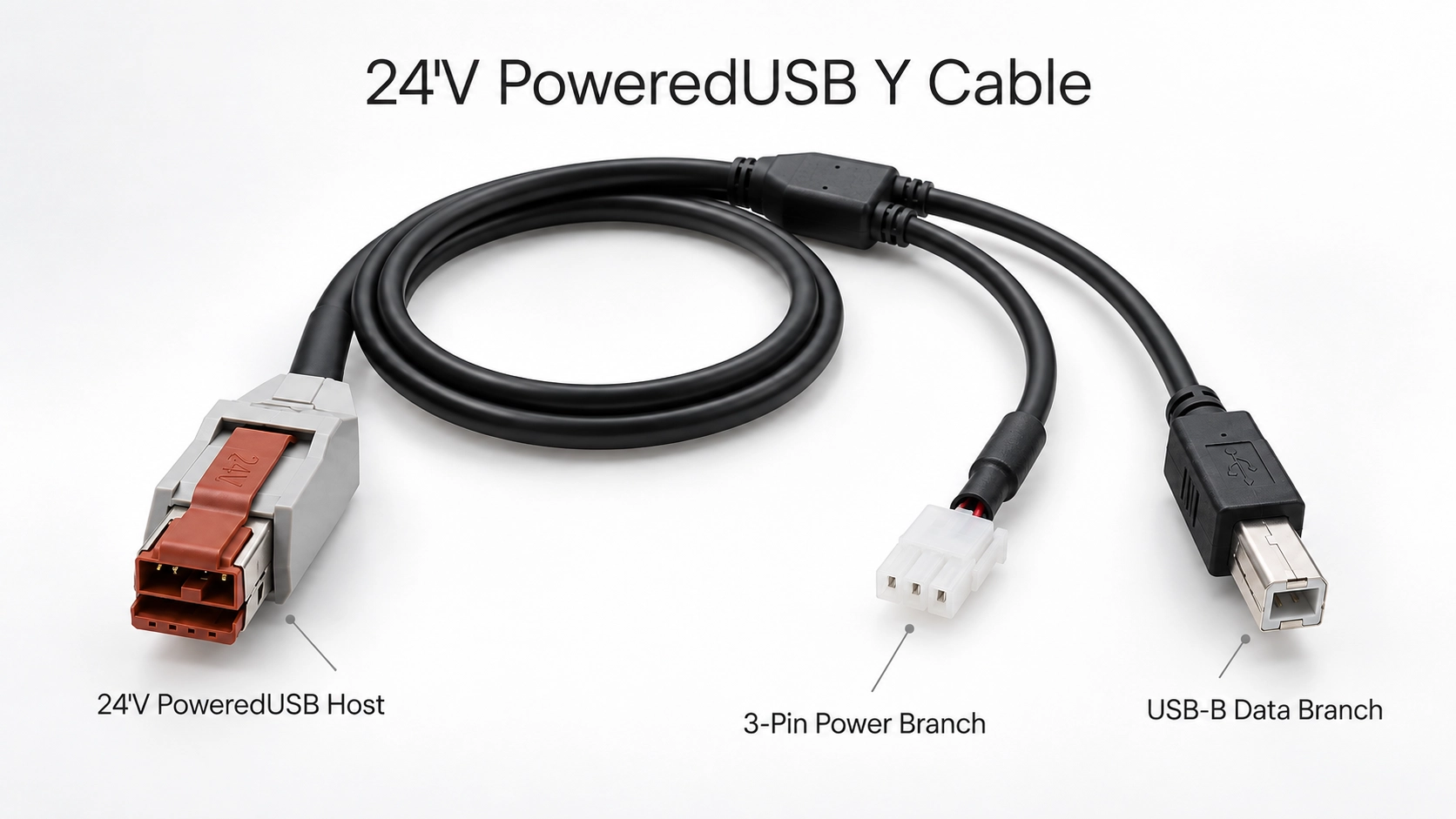
A three-pin connector should never be identified only by the number of contacts. Different printer power connectors can use three positions while having different housing shapes, keying, contact geometry and electrical assignments.
Before a sample is made, the connector should be confirmed from a part number, dimensional drawing, mating sample or a clear photo of the equipment socket. The wiring drawing should also identify polarity and indicate whether all three positions are used.
This avoids treating different three-position printer power interfaces as interchangeable simply because they have the same pin count.
For a Y cable, the location of the split is an engineering dimension rather than a cosmetic choice. If it is too close to one connector, the second branch may not reach its socket. If it is placed unnecessarily far back, excess branch cable can make the installation harder to organize.
Goochain can define the USB-B branch and 3-pin power branch separately from a fixed reference point on the molded junction. A rear-panel sketch showing the distance between both printer sockets is often enough to establish a practical first layout.
For printers that use one combined device-side interface instead of separate USB and power sockets, a 24V PoweredUSB to 1x8 Pin printer cable represents a different connection architecture and should be selected according to the fitted printer interface board.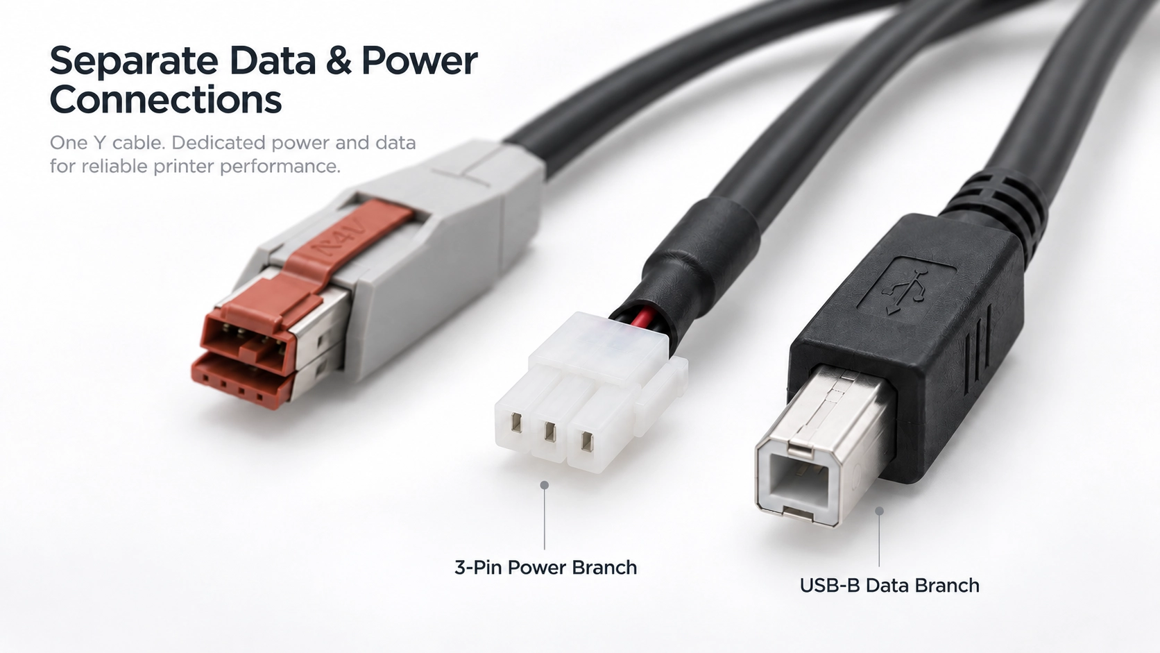
This cable is a passive wiring assembly. It routes the defined USB connection and the available 24V host supply according to the approved pin assignment.
It does not create, regulate or convert a 24V output by itself. The host equipment must provide the correct supply, and the connected printer must be designed for the corresponding power input.
For this reason, the PoweredUSB keying, printer power requirement and connector pin assignment should all be checked before the cable is released for production.
POS printers are often installed beneath counters, close to walls or beside other peripheral equipment. The cable therefore needs enough room not only to reach the sockets, but also to leave the connector bodies without being forced into an immediate sharp bend.
When defining the cable, provide the distance from the host to the printer, the location of both device-side sockets and the available clearance behind the equipment. Straight or angled exits can then be reviewed according to the actual installation.
A simple rear-view photo with approximate dimensions is often more useful than specifying only a total cable length.
PU07 is treated as a configurable PoweredUSB cable family rather than a universal replacement cable. The production drawing is built around the host, printer connectors and installation layout.
Typical customization items include:
For this type of cable, a sample should be evaluated with the intended host and printer rather than checked only on a workbench. The two branches should reach their sockets without tension, the connectors should seat correctly and the molded junction should remain clear of the surrounding equipment.
Once the mechanical arrangement and wiring are approved, the accepted drawing and sample become the reference for repeat production. Goochain's cable manufacturing and quality control process can then apply the agreed checks for connector fit, wiring, branch dimensions, appearance and labeling.
The USB Type-B branch provides the USB connection to equipment fitted with the corresponding USB-B socket. Its exact communication requirements should be confirmed with the host and printer specification.
The 3-pin branch connects the specified 24V supply to the printer's separate power input according to the approved wiring map and connector pin assignment.
No. A three-pin count does not define the connector. Housing geometry, keying, mating dimensions and pin assignment must be confirmed before production.
Yes. Each branch can be dimensioned independently from a defined reference point on the split overmold to the connector reference face.
Yes. The split position can be reviewed according to the spacing between the printer's USB-B and power sockets, the available rear clearance and the required service access.
No. This passive cable routes the supply provided by the compatible host. If voltage conversion or regulation is required, that function must be provided by a separately designed electronic circuit.
No. Compatibility depends on the printer's USB interface, power connector, required voltage, connector geometry and approved pinout. These details should be checked before ordering.
Provide the printer model or equipment type, a rear-panel photo, the 3-pin connector reference, pin assignment, required USB-B and power branch lengths, total cable length and estimated order quantity. A reference cable or mating connector sample is particularly useful when the connector series is not known.
Yes. Prototype samples can be used to confirm connector mating, Y-split position, branch lengths, wiring and installation clearance with the actual POS host and printer before the production specification is finalized.
Keep required fields minimal. Attach drawings/photos for accurate quoting.
Tip: A simple installation photo often saves 2–3 rounds of questions.
Quotation 1–2 days; development 15–20 days; mass production 20–25 days (project dependent).
Yes. Reference sample + requirements helps confirm drawings and test plan.
Depends on materials and complexity. We support prototypes and scalable mass production.


 English
 简体中文
简体中文  Deutsche
  Italian
  français
  Español
  Nederlands
  日本語
日本語  한국어
한국어  عربى
عربى  português
  Türk
Türk