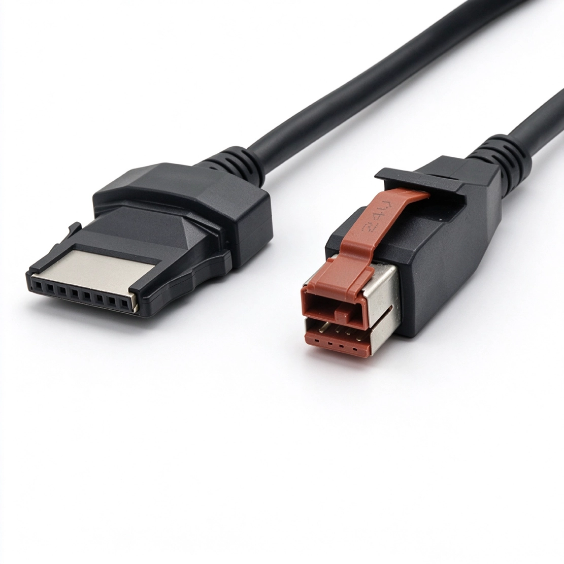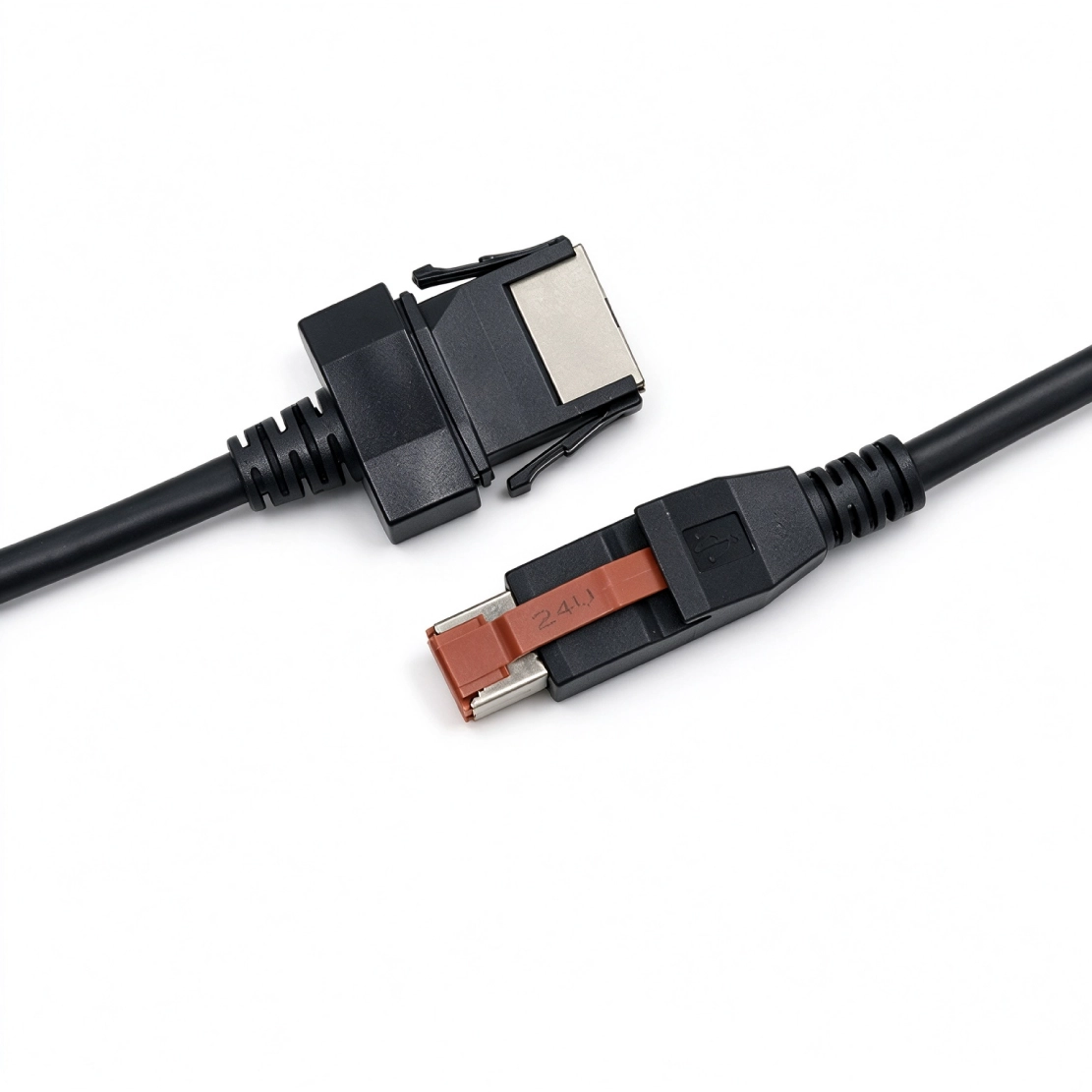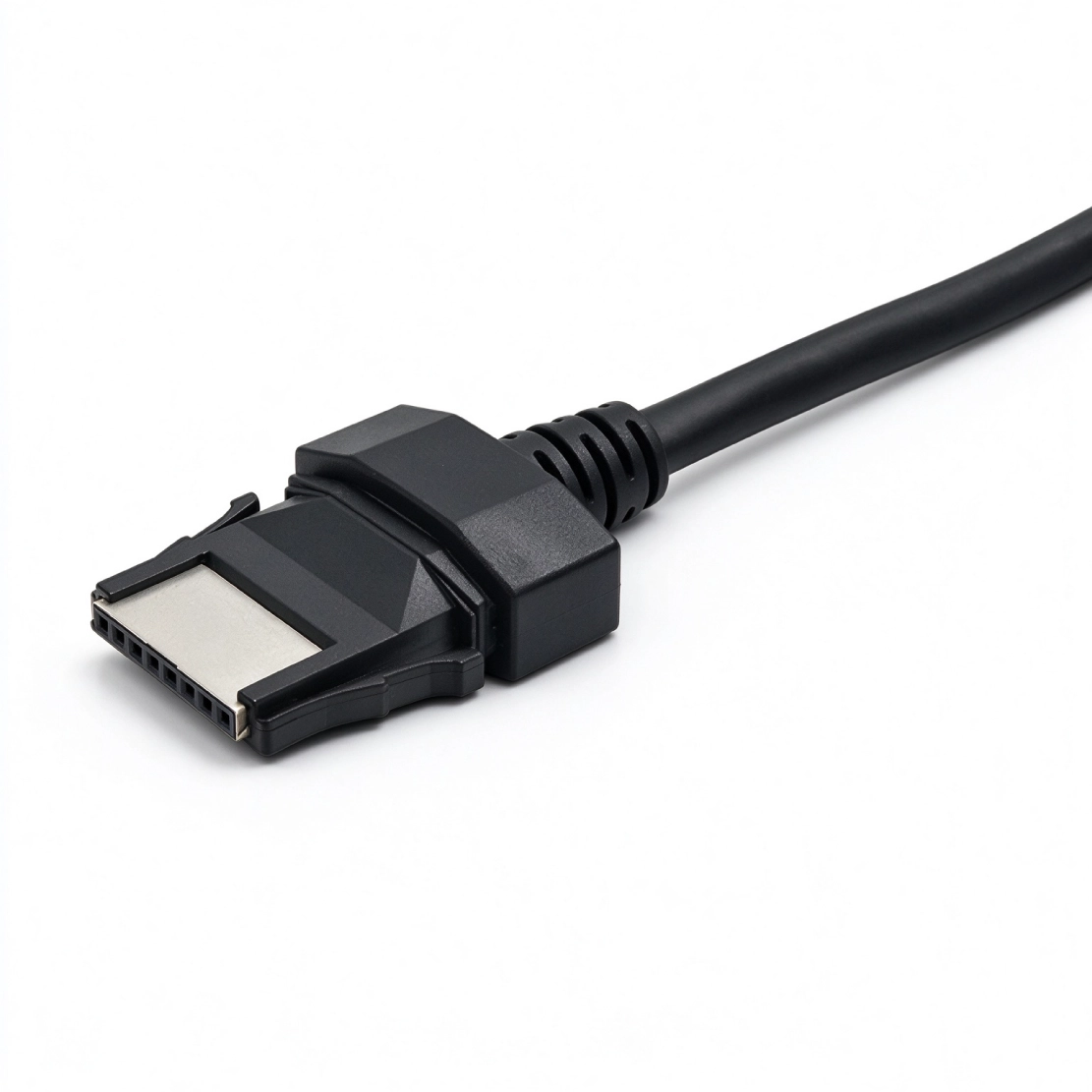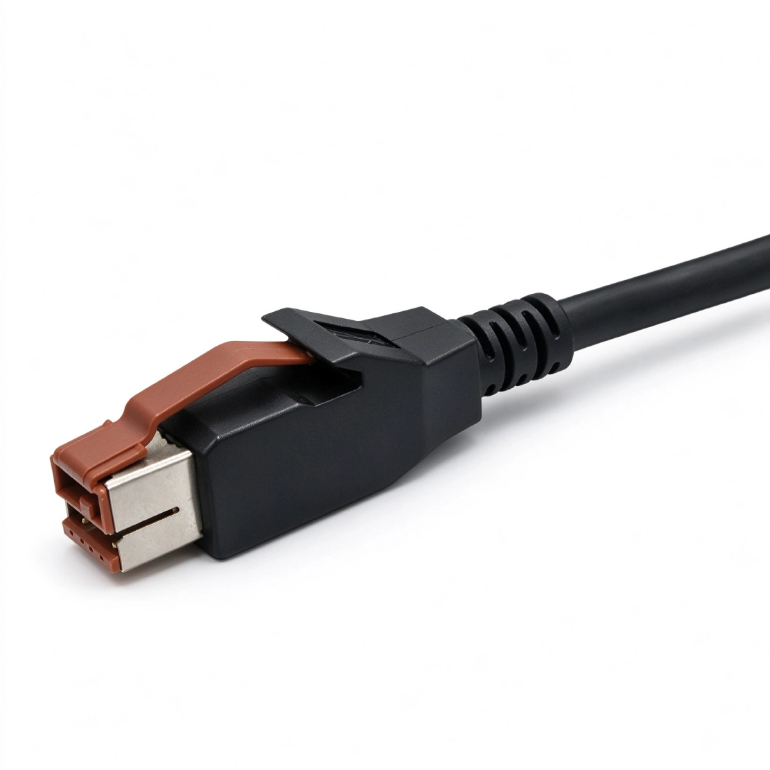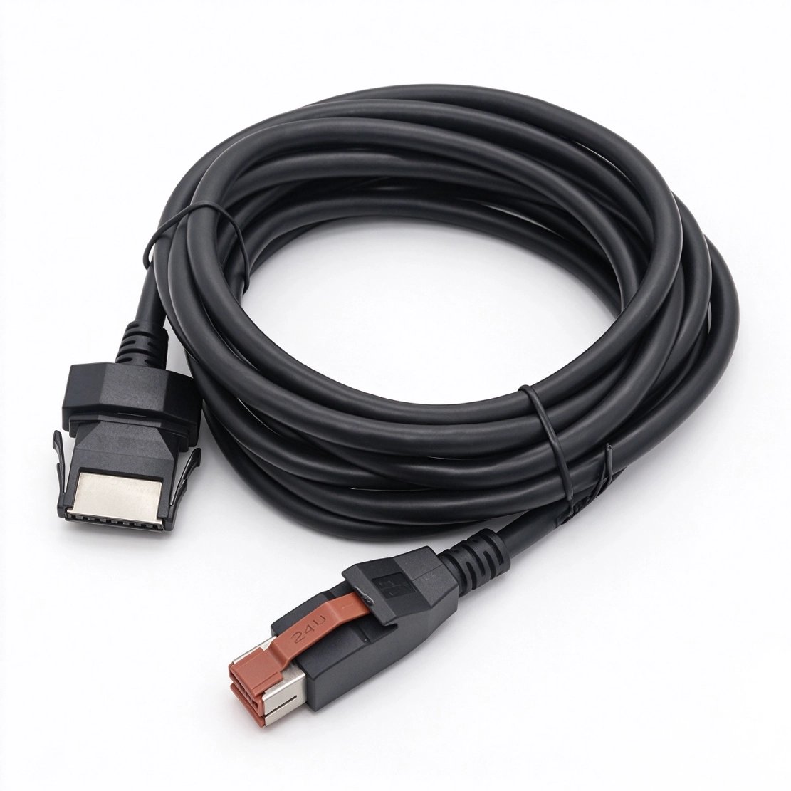


Power and USB in one cable, with a locking single-row 1x8 connector matched to the printer's interface board.
The printer's interface board determines whether this cable is the right fit. Goochain manufactures 24V POWEREDUSB to 1x8 pin printer cables for equipment that carries USB data and power through one combined socket. A voltage-keyed host plug connects to a locking, single-row eight-position printer connector. We match the device-side wiring and connector geometry before setting the cable length and molded exit for the available rear clearance.
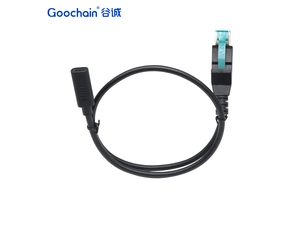
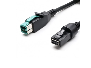
A replacement printer cable is easier to specify when you can see the connection behind the printer. Goochain's 24V POWEREDUSB to 1x8 Pin POS Printer Cable connects a 24V-keyed host port to a matching single-row, eight-position printer interface. On printers that support this arrangement, the cable carries the defined power and USB connections along one route.
The assembly is developed around the fitted interface board, connector geometry and wiring. This makes it suitable for a defined replacement requirement or an OEM printer installation where the cable needs to fit the equipment layout.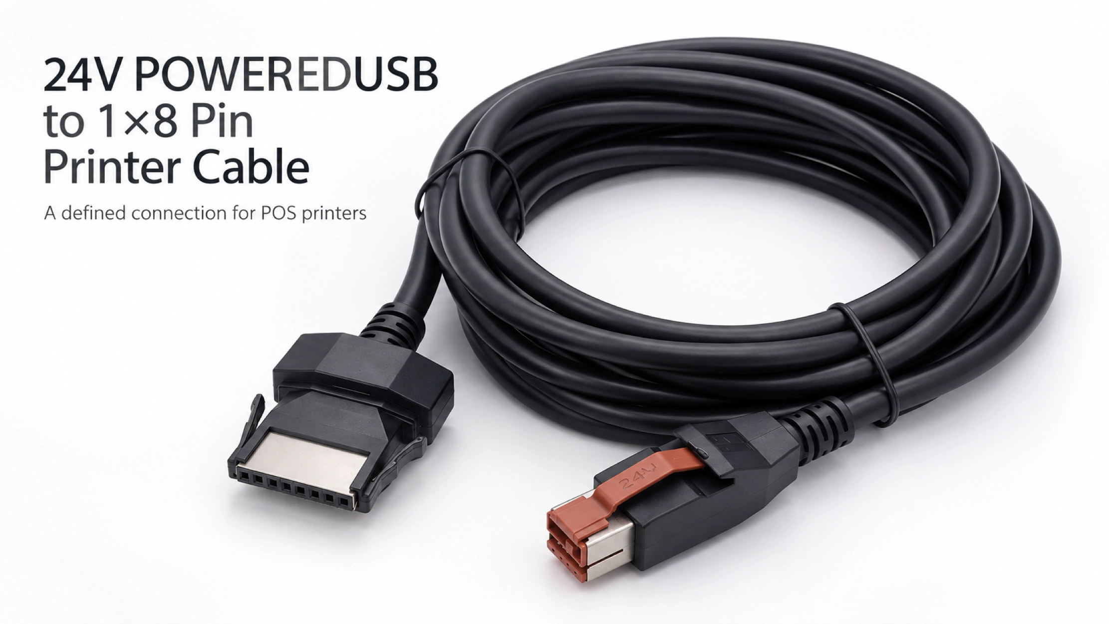
Printers from the same family can be supplied with different interface boards. The model name on the case is a useful starting point, but the rear socket and its electrical specification determine which cable is required.
For a replacement, provide the printer model, interface-board identification and a clear photo of the socket. An existing working cable or mating connector drawing helps confirm the latch, keying and pin assignment. These details are particularly useful when several printer versions are installed across different checkout locations.
With the appropriate printer interface, a single cable run carries the required supply and USB communication between the POS host and printer. The device end uses eight positions in one row, with the power and signal paths defined by the approved wiring map.
A 2×4 connector also has eight positions, but its two-row layout is a different mating format. Likewise, a printer with separate USB and power sockets needs an assembly that matches those inputs. Other connection formats are available in our PoweredUSB Cable range.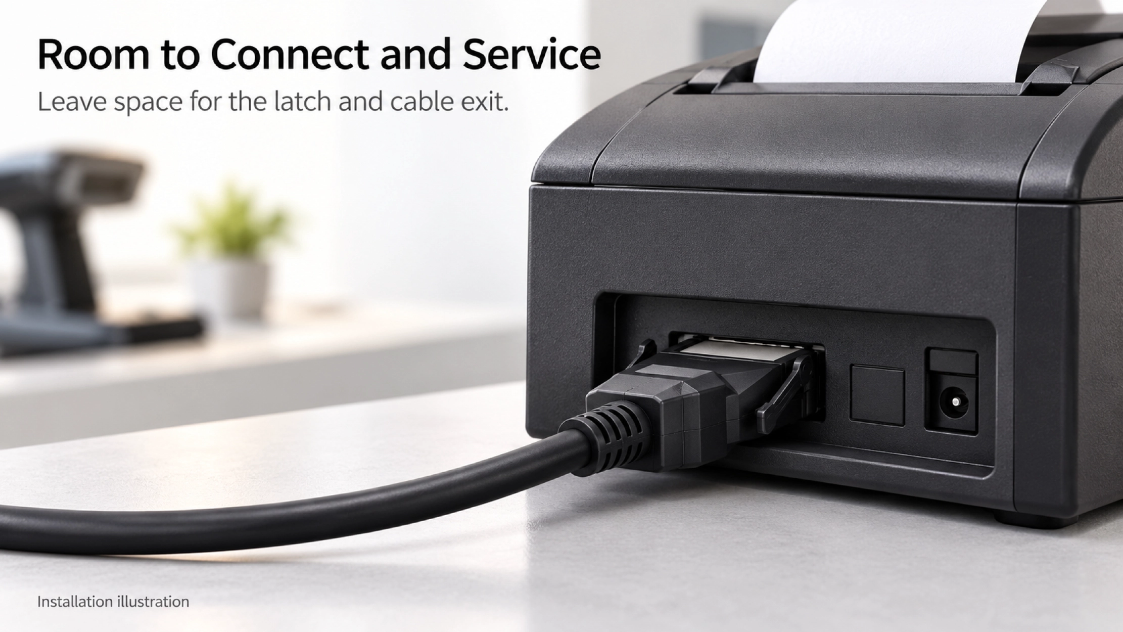
A printer may sit close to a wall, beneath a shelf or beside other equipment. The connector body and molded cable exit need enough clearance for the cable to turn naturally. The latch also needs to remain accessible when the printer is disconnected for service.
Goochain can review the length, overmold and strain relief against that space. A rear-view installation photo shows where the cable will leave the printer and where it can be supported. For equipment that needs to move during maintenance, include the required service travel when defining the route.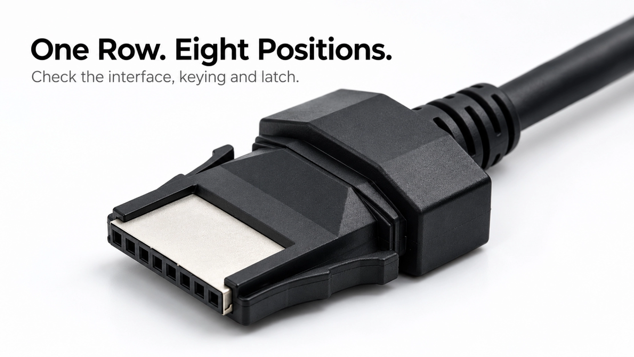
Sample evaluation should cover the complete connection: host port, cable and fitted printer interface. Alongside connector fit and wiring checks, confirm the required USB communication and printer operation under the agreed working conditions. Cable construction is selected with the route length and printer load in mind.
When a sample is accepted, record the interface-board reference, connector details, pin map, cable length and molded exit. This gives repeat orders a clear specification and helps distinguish assemblies that look similar but serve different printer configurations.
Goochain manufactures custom cable assemblies at its 5,000 m² factory in Dongguan, China. Our OEM and ODM support for powered USB printer projects includes connector review, sample development, cable construction, overmolds, strain relief and labeling.
The approved drawing and sample define the production build, while the agreed inspection plan sets out the checks required for that assembly. Our Factory & Quality page explains the incoming, in-process and final inspection stages.
No. Compatibility depends on the exact printer interface, fitted board and pinout. Confirm those details even when the printers share a brand or product family.
A custom structure can be reviewed against the mating connector, available clearance and tooling requirements. The finished connector must still engage and release correctly.
Send clear photos of both mating faces and any identification markings. A working sample helps establish the mechanical and wiring reference; the printer and host details are still needed for functional evaluation.
Start with a Photo of the Printer's Rear Interface
Include the printer model, interface-board reference, available pinout and required cable length. Add the printer power requirement, a photo of the installation space and your expected quantity. With these details, we can review the 1×8 connection and define the first sample.
Keep required fields minimal. Attach drawings/photos for accurate quoting.
Tip: A simple installation photo often saves 2–3 rounds of questions.
Quotation 1–2 days; development 15–20 days; mass production 20–25 days (project dependent).
Yes. Reference sample + requirements helps confirm drawings and test plan.
Depends on materials and complexity. We support prototypes and scalable mass production.


 English
 简体中文
简体中文  Deutsche
  Italian
  français
  Español
  Nederlands
  日本語
日本語  한국어
한국어  عربى
عربى  português
  Türk
Türk