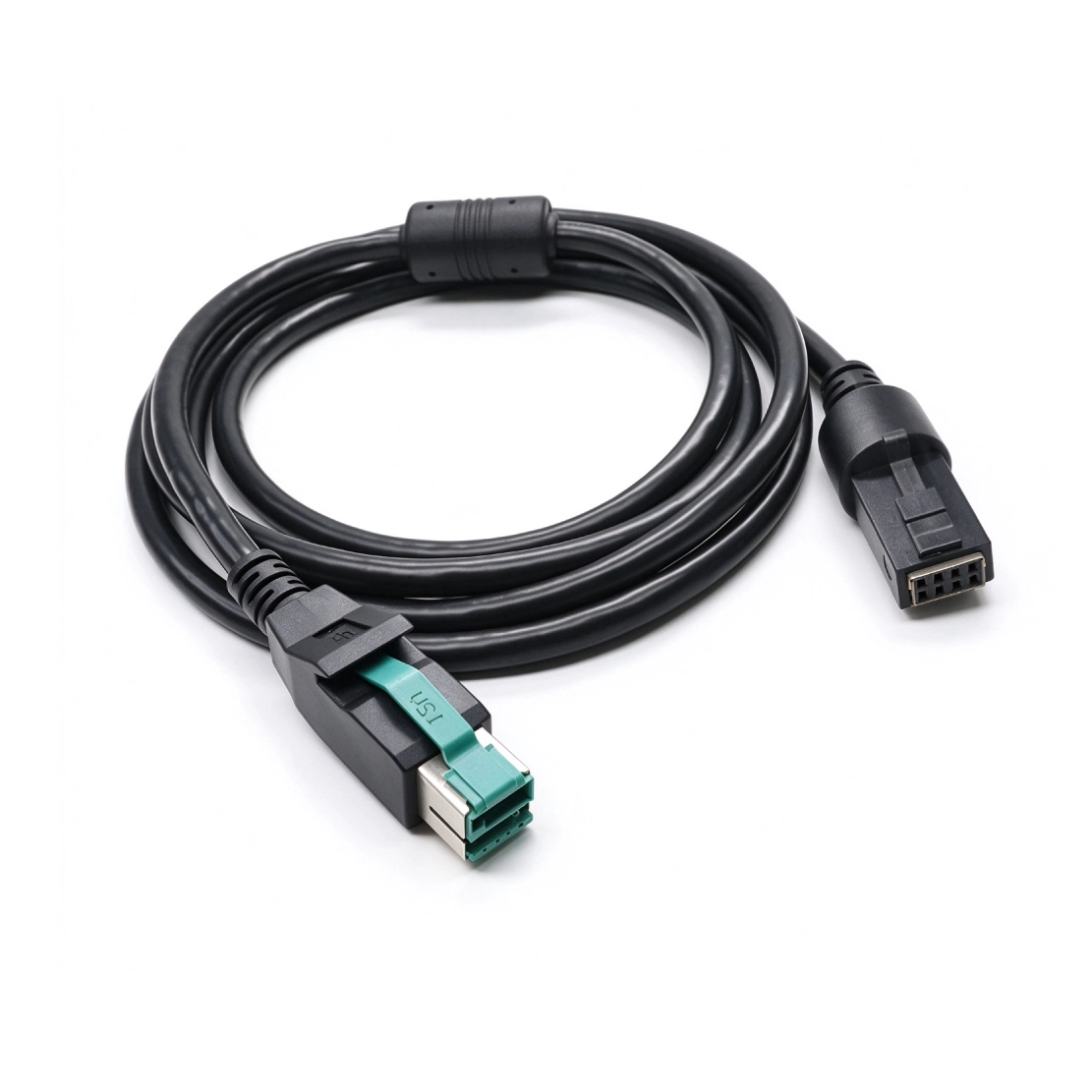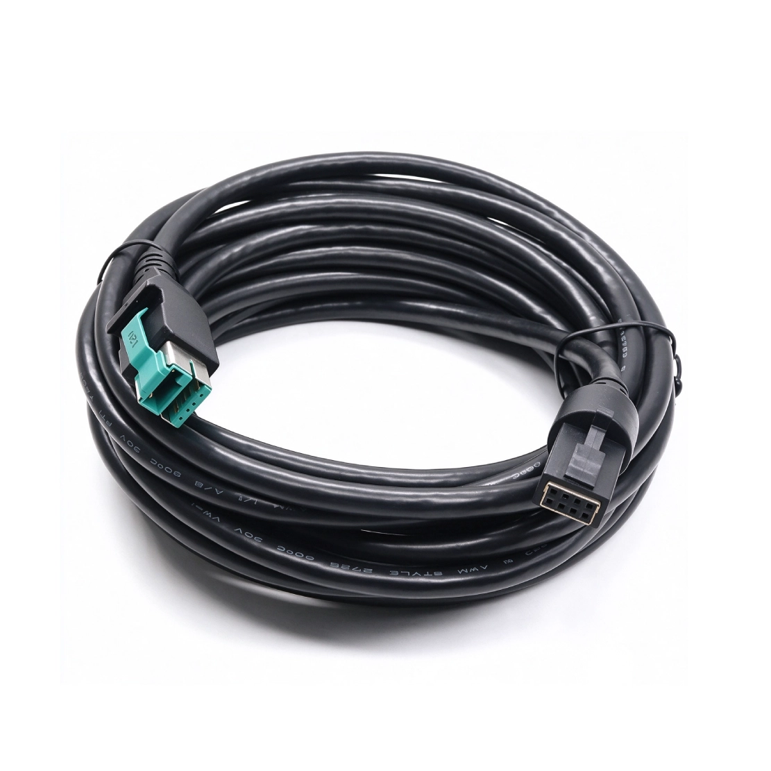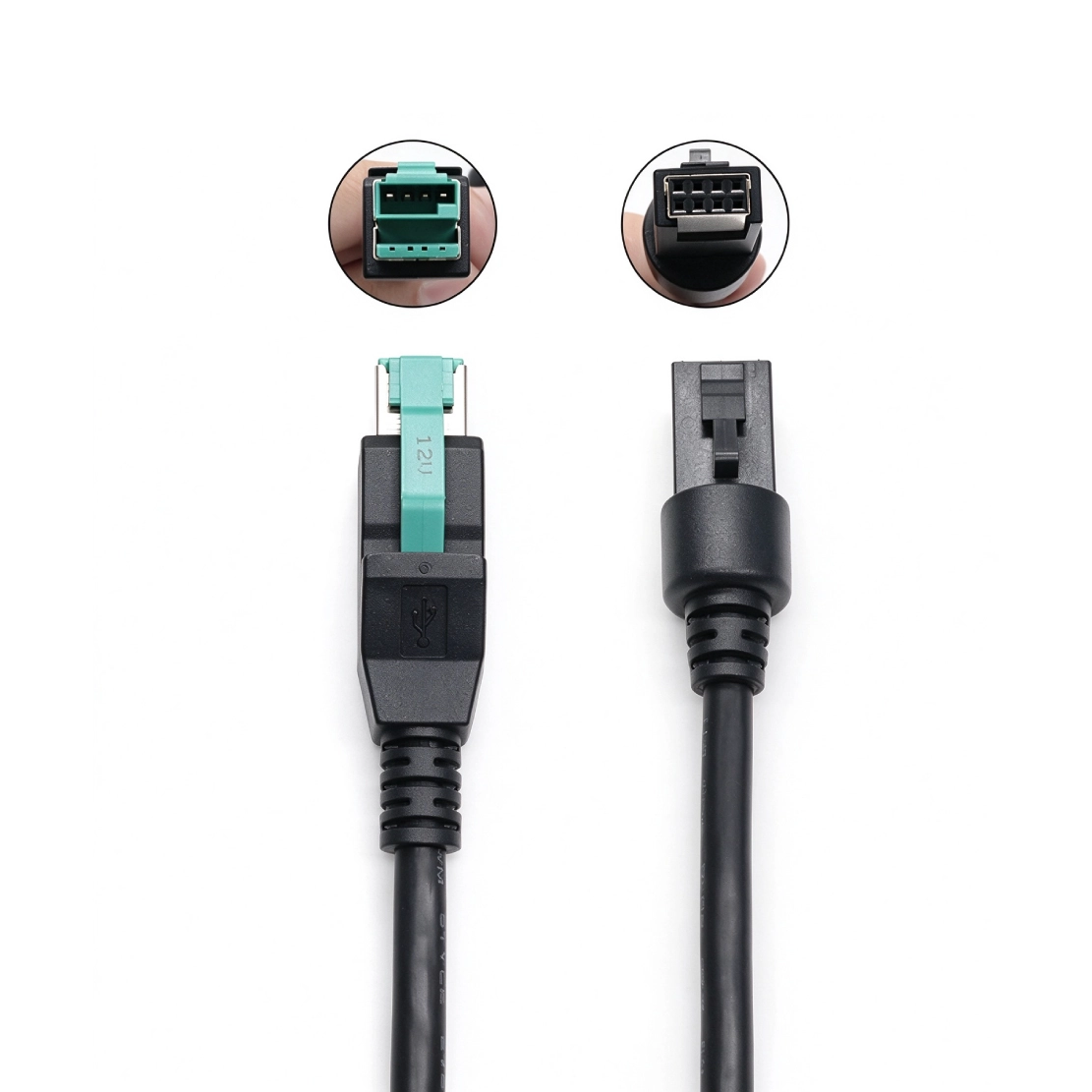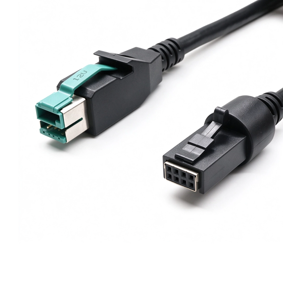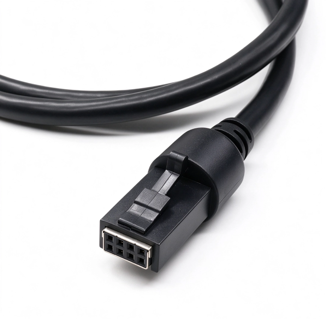


A 12V host connection and a two-row device plug, matched to the peripheral's keying, latch and power-and-data pinout.
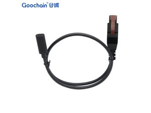
Ordering this cable starts at the peripheral socket. Its 2x4 layout has eight contact positions in two rows, but the latch, keying and wire map determine which assembly fits. Goochain makes the cable with a 12V POWEREDUSB male host plug and an equipment-matched 2x4 device connector, carrying the specified USB and power connections in one run. Cable length, conductor construction and molded exits can be developed from a mating drawing or reference sample.
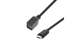
When a POS peripheral has a single 2×4-pin socket, the cable needs to match more than the supply voltage. Goochain's 12V POWEREDUSB to 2×4 Pin Cable connects a compatible host port to that device interface, carrying USB data and power through the wiring defined for the equipment. It is a direct host-to-device assembly, with one eight-position connector at the peripheral end.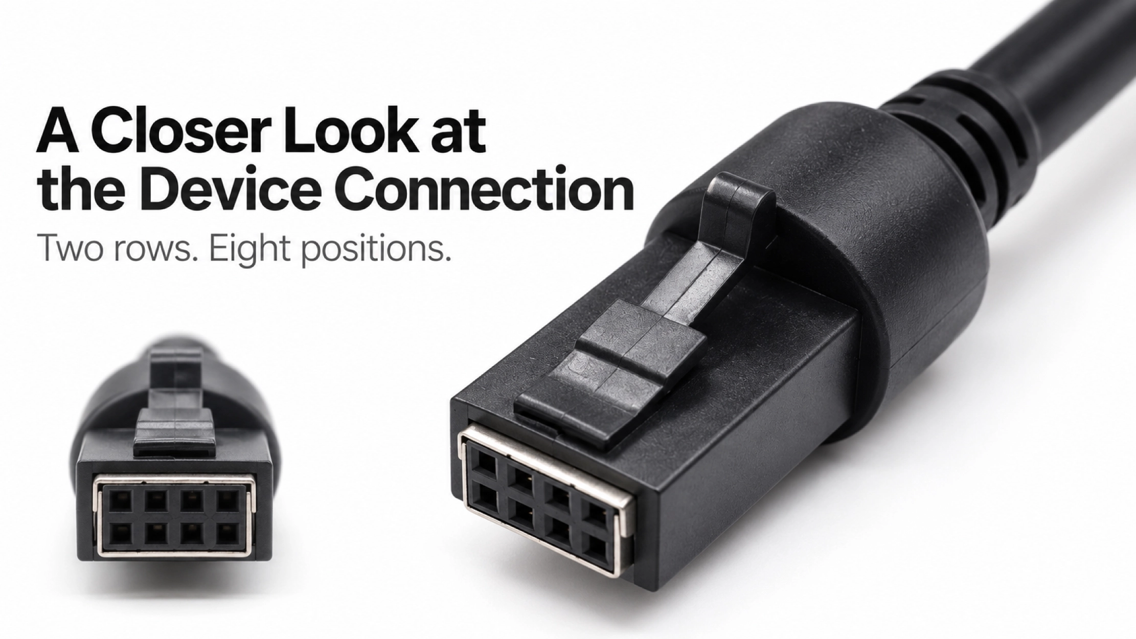
A front-facing photo of the device socket is often the most useful starting point. Two rows of four contacts tell us the layout, but the housing shape, contact pitch, keying and latch determine whether the cable will mate correctly. The position of the socket inside a recess also affects how much room is available for the connector body.
For a replacement cable, send the existing assembly and the equipment model where possible. For a new design, a mating connector part number or drawing helps define the device end before sample production. If the peripheral uses another interface, our PoweredUSB Cable range includes other device-end configurations.
The reference construction below describes the listed 3 m version. For an OEM order, the approved drawing records the selected length, connector details and electrical requirements so purchasing and engineering work from the same specification.
| Item | Reference / Order Definition |
|---|---|
| Host connection | 12V-keyed POWEREDUSB male |
| Device connection | Single 2×4-position male connector; mating housing and pin assignment to be confirmed |
| Reference length | 3 m; custom lengths reviewed for the installation |
| Reference conductors | 26 AWG data conductors and 20 AWG power conductors |
| Reference cable body | Approximately 6.5 mm outer diameter; double-shielded construction |
| USB data | Listed version: up to 480 Mbps; modified assemblies require validation for the specified system |
| Custom development | Cable length, conductor construction, shielding and connector overmold, subject to design review |
A connector can fit mechanically while its wiring is wrong for the device. The assembly drawing therefore needs to identify each host contact and its destination at the 2×4 connector, including the power, return and USB signal connections required by the peripheral.
Connector views should be marked as mating-face or wire-side views, with a clear pin-one reference. This avoids a mirrored pin assignment when a sample is reproduced. Cable colors alone are not a substitute for that drawing, particularly when more than one supplier or equipment revision is involved.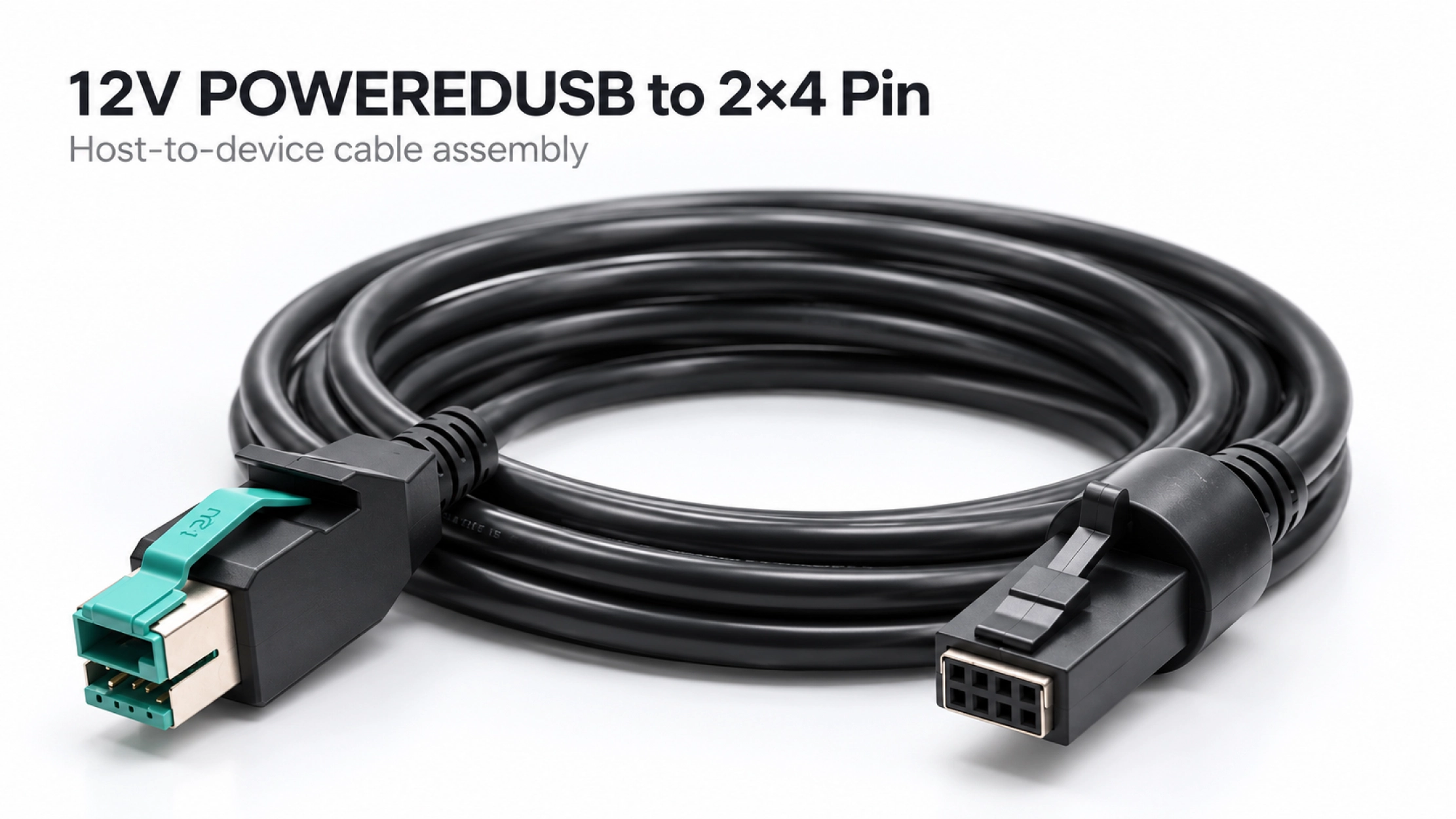
Behind a checkout terminal or inside a kiosk, the shortest cable is not always the easiest to install. The route needs room for the molded cable exit, a gradual bend and access to the connector latch. A cable trapped against a cover can make a routine device replacement unnecessarily difficult.
An enclosure photo or section drawing lets us review these details with you. We can then assess the cable length and overmold geometry around the actual mounting position. Power conductor selection also takes account of the peripheral load and route length; the 12V designation alone does not define the current capacity of the complete assembly.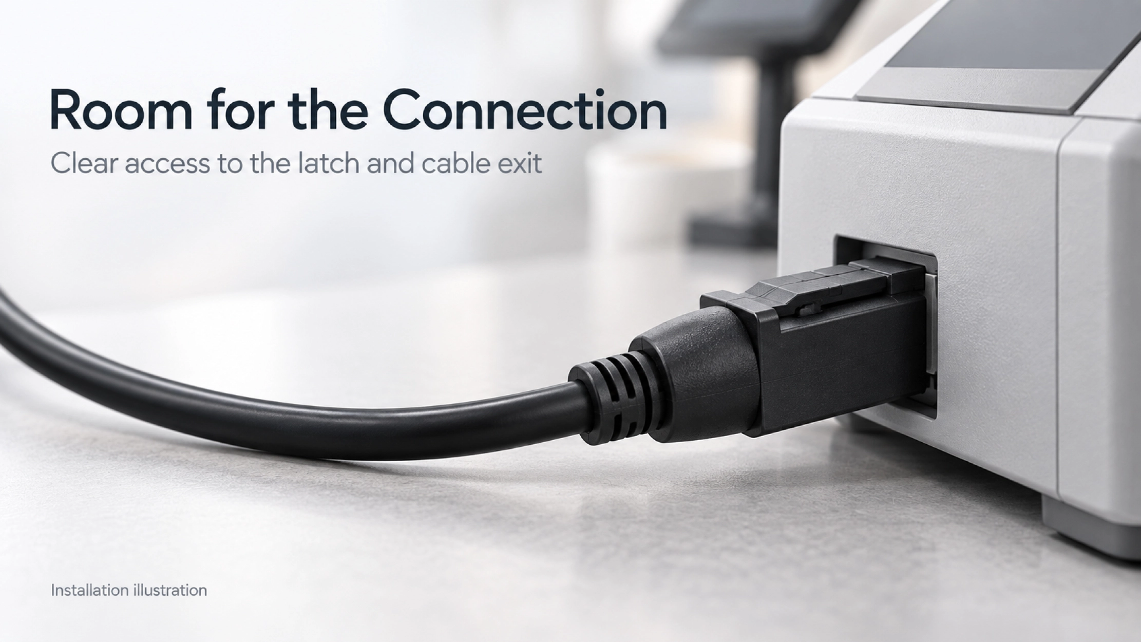
Goochain supports OEM and ODM powered USB cable development at its 5,000 m² Dongguan factory. A project can start from an equipment drawing or a reference cable. Connector selection, pin mapping and the molded exit are reviewed before the sample is evaluated on the intended hardware.
Once the sample is approved, its connector details, wiring and dimensions become the production reference. The agreed inspection plan can cover mating fit, continuity, shorts, appearance and functional checks. Our Factory & Quality page explains the incoming, in-process and final inspection stages behind this work.
No. This assembly uses one device connector with eight positions arranged in two rows of four.
A photo helps identify the housing, but it does not establish the wiring. A part number, pinout or working reference sample is needed to confirm the electrical configuration.
A similar device-end housing does not make the assemblies interchangeable. Match the host voltage, connector keying and device pin assignment to the equipment specification.
Have the device socket or an existing cable?
Send a clear connector photo, the equipment model and your required cable length. Include the mating part number or pin map, operating load and order quantity if available. These details help us identify the right 2×4 connector and define a sample for your installation.
Keep required fields minimal. Attach drawings/photos for accurate quoting.
Tip: A simple installation photo often saves 2–3 rounds of questions.
Quotation 1–2 days; development 15–20 days; mass production 20–25 days (project dependent).
Yes. Reference sample + requirements helps confirm drawings and test plan.
Depends on materials and complexity. We support prototypes and scalable mass production.


 English
 简体中文
简体中文  Deutsche
  Italian
  français
  Español
  Nederlands
  日本語
日本語  한국어
한국어  عربى
عربى  português
  Türk
Türk