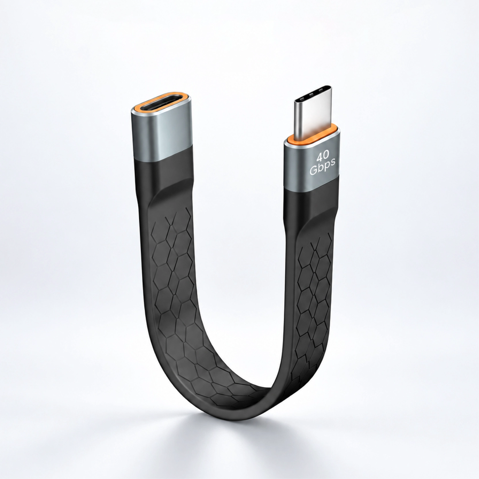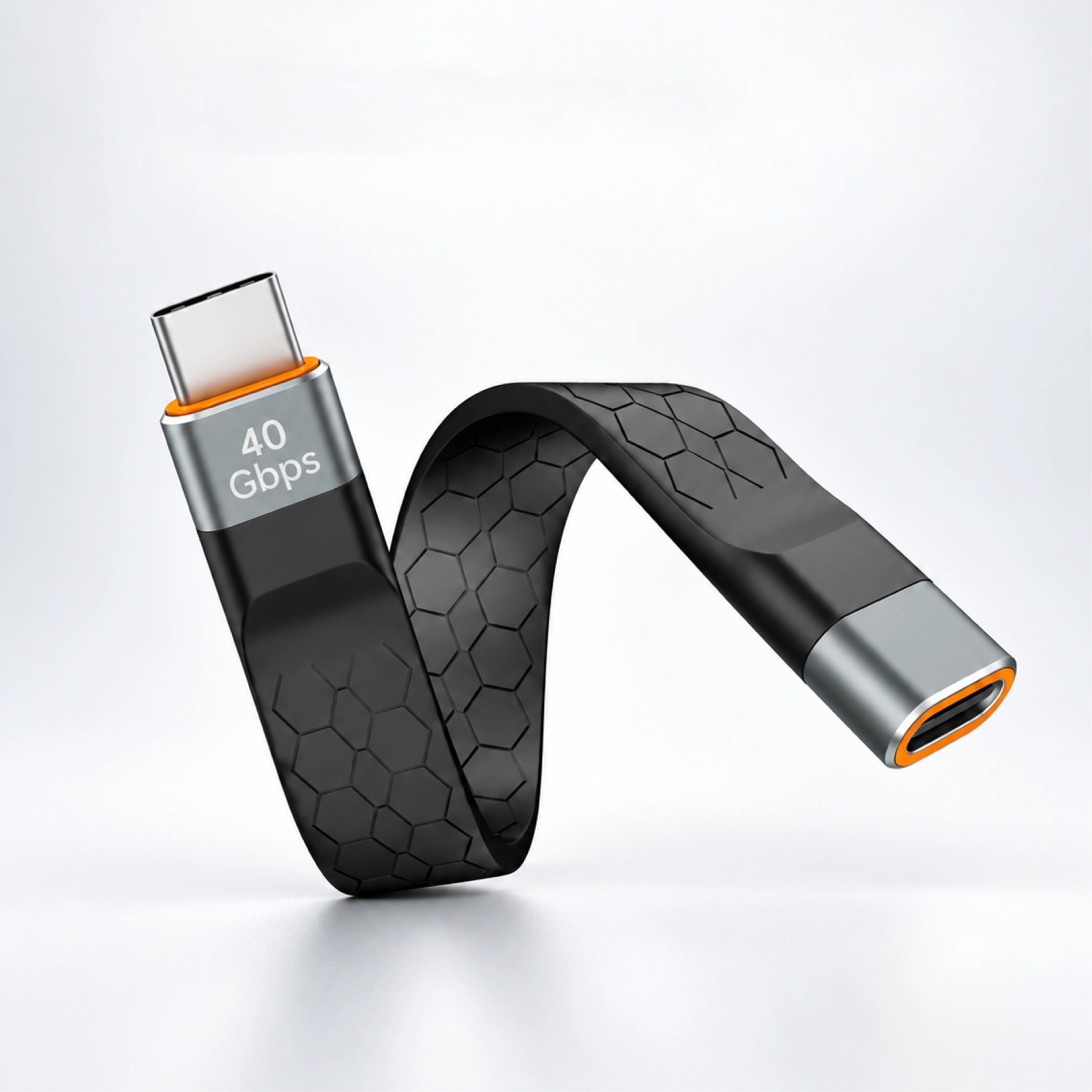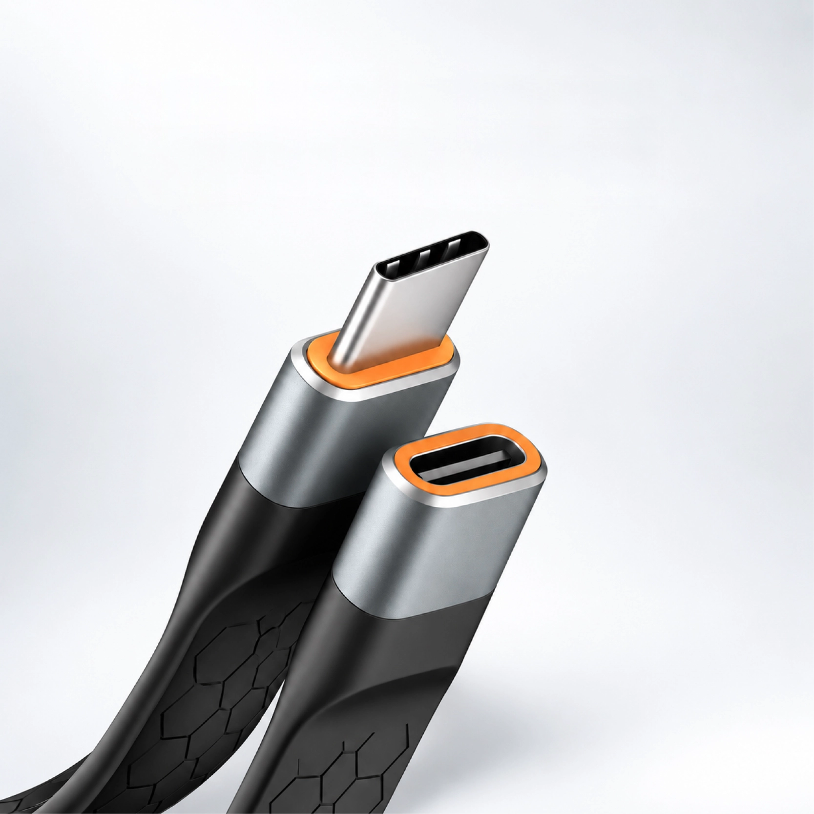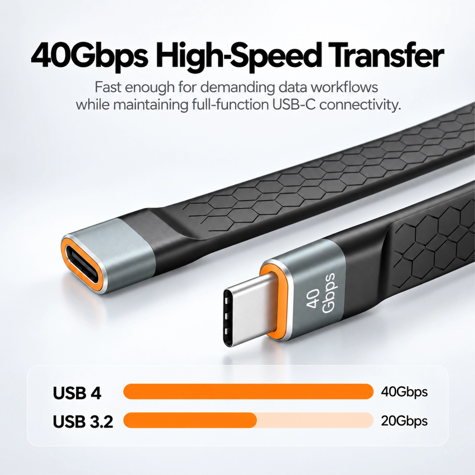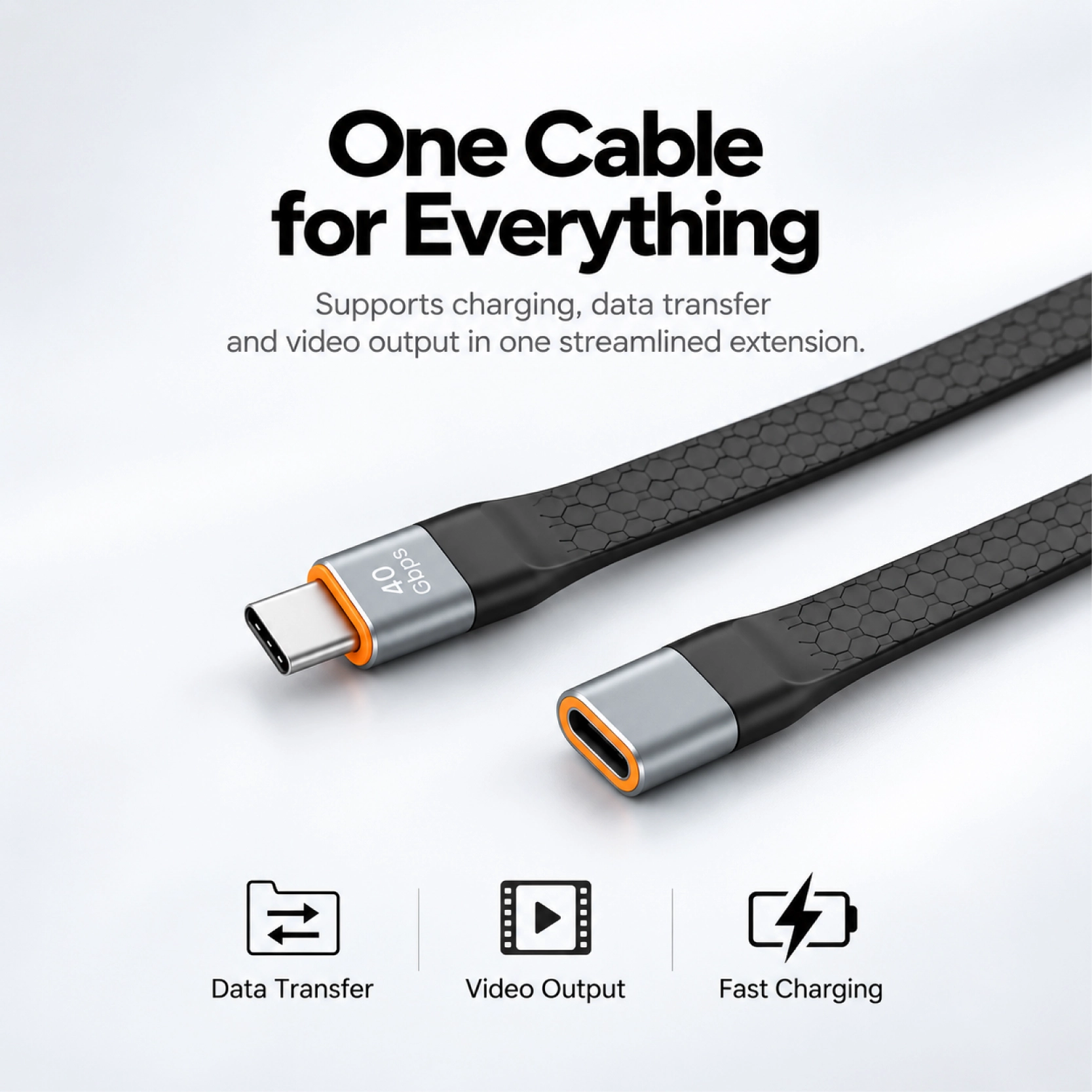


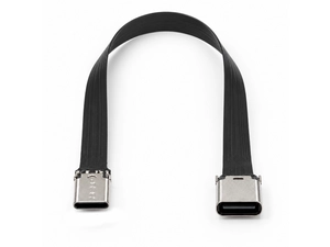
A finished male-to-female USB-C extension for compact routes that need a flat cable, a protected outer body and a supported receptacle.
The value of this cable is not simply that it is flat. It relocates a USB-C connection from a male plug to a female receptacle while keeping the route low-profile and giving the FPC a finished protective body. The male end can plug into an internal or recessed USB-C port, and the female end can be positioned where the equipment needs access for service or an external cable. Compared with a bare FPC extension, the molded body is easier to handle during assembly and protects the cable route where it may remain partly exposed. Goochain can develop the length, molded profile, connector directions and receptacle support around the actual enclosure, then build samples for fit and electrical evaluation before the production version is released.
A USB-C port can be easy to reach on a bare device and awkward to use once that device is installed. This male-to-female extension moves the connection point along a flat cable route, leaving a female socket where the next cable can be plugged in.
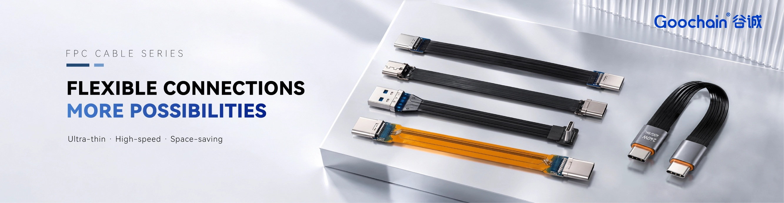
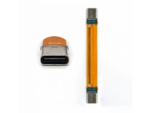
Inside the assembly is a flexible printed circuit (FPC). A full outer overmold covers the cable body and forms its finished profile through the connector transitions. Goochain manufactures the extension for layouts that need both an accessible connection and a covered cable surface.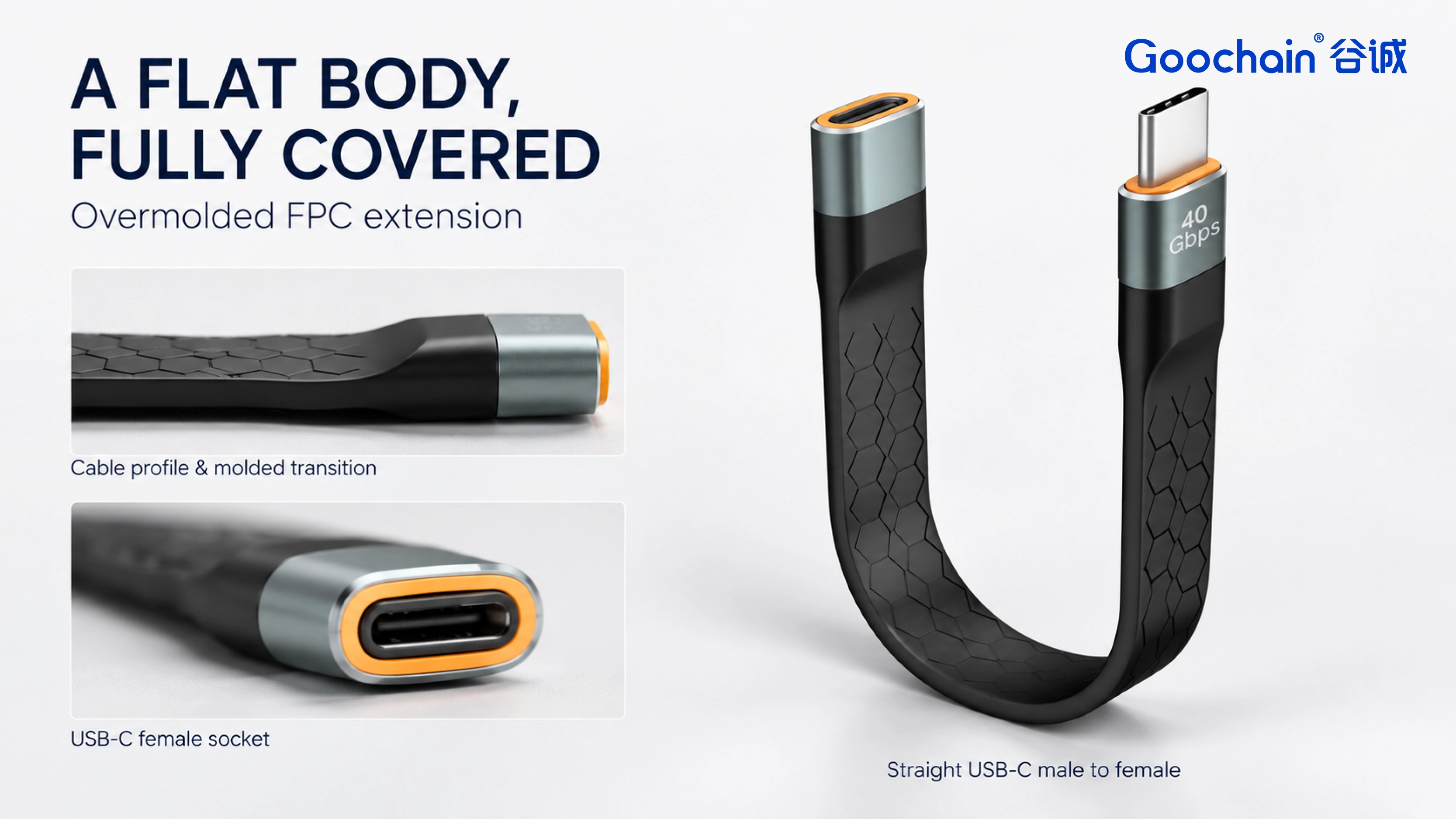
The male plug connects to the original device port. The female end becomes the accessible connection for a separate USB-C cable. Positioning that socket is part of the installation: there needs to be room for the mating plug, its housing and the direction in which its cable leaves.
The female socket also needs suitable support. A bracket or enclosure feature can hold the receptacle while a cable is inserted or removed, rather than leaving the flexible section to carry that movement. The molded covering gives the cable its outer form; the equipment still provides the mounting arrangement.
A covered extension is useful when part of the route remains visible or is handled during installation and servicing. The outer molding encloses the FPC and provides a continuous handling surface along the flat body.
That covering occupies space. When replacing an FPC assembly without a full outer overmold, check the finished width and thickness, the larger transitions near the connectors and the room available for each bend. A route that fits the central section may still be too tight around a plug housing.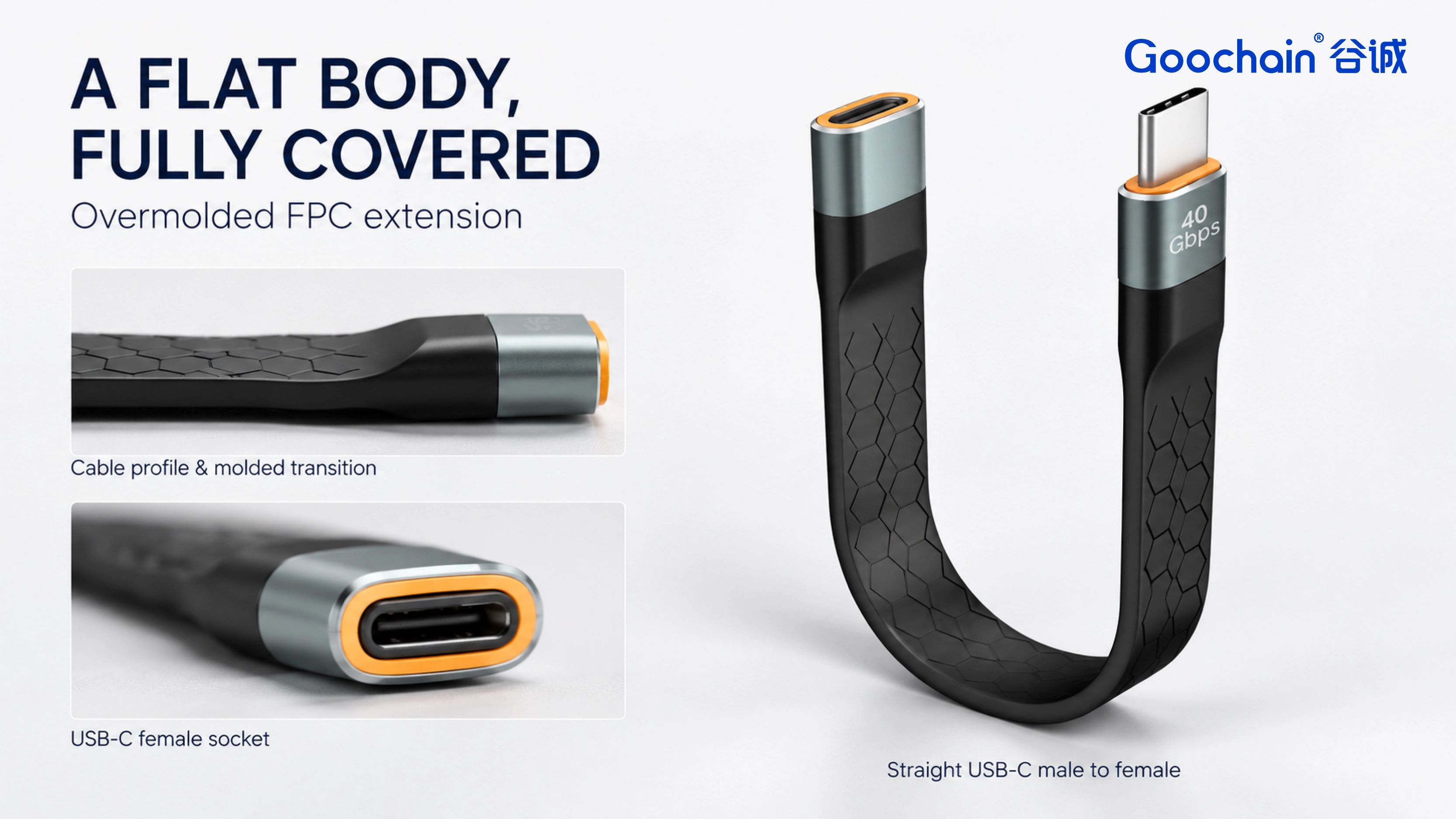
| Item | Configuration |
|---|---|
| Connector pair | USB-C male plug to USB-C female receptacle |
| Cable body | Internal FPC enclosed in a full outer overmold |
| End orientation | Straight or angled combinations, according to the selected configuration |
| Length and profile | Cable length, molded outline and connector transitions to the approved drawing |
| Electrical capability | Data rate, power and display functions defined for the selected extension and complete connection |
| Manufacturer | Goochain, Dongguan, China; custom OEM cable assembly |
An extension sits between the device port and another cable. Its electrical requirements therefore need to account for that downstream cable, the total connected length and the equipment at both ends. Data, charging and display requirements are assessed for that arrangement; the molded exterior alone does not establish a performance rating.
If the installation simply connects two USB-C sockets, a male-to-male assembly such as the USB-C 240W cable may be the more direct connector arrangement. Its power rating applies to that separate product.
At Goochain, the molded outline and connector integration are reviewed together, followed by assembly and electrical inspection. The development work centers on the socket position, installed route and required functions. For the broader choices behind that layout, see USB-C FPC Cable Selection for OEM Equipment.
Yes. Straight and angled combinations can be reviewed for the available space. The end directions and molded transitions are set together so the cable reaches its installed position without being forced into a twist.
A molded exterior does not establish a waterproof rating. The connector openings and any required seals need their own design and verification.
A panel-mount flange or screw fixing is not specified for this version. The equipment design should provide suitable support for the female receptacle; any integrated fixing needs to be defined separately.
Keep required fields minimal. Attach drawings/photos for accurate quoting.
Tip: A simple installation photo often saves 2–3 rounds of questions.
Quotation 1–2 days; development 15–20 days; mass production 20–25 days (project dependent).
Yes. Reference sample + requirements helps confirm drawings and test plan.
Depends on materials and complexity. We support prototypes and scalable mass production.


 English
 简体中文
简体中文  Deutsche
  Italian
  français
  Español
  Nederlands
  日本語
日本語  한국어
한국어  عربى
عربى  português
  Türk
Türk