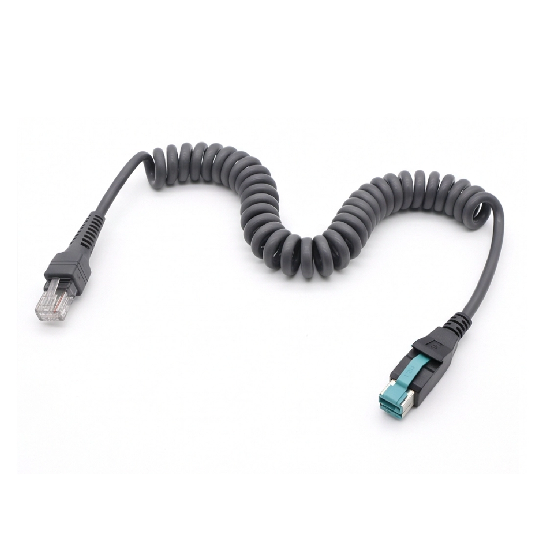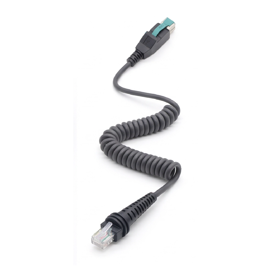


A custom coiled cable with defined working reach and straight tails, built around the scanner’s normal handling distance.
The useful length of a handheld scanner cable is the distance an operator can reach comfortably—not the distance the coil can survive at its maximum stretch. Goochain develops coiled PoweredUSB scanner cables around that daily movement. A straight tail is retained at each end to keep the coil away from the connectors, while the coil section is positioned to rest near the scanner stand or checkout counter. Host voltage keying, scanner-side connector, pinout, jacket and operating reach are specified for the actual equipment before sample approval.
Goochain develops coiled POWEREDUSB scanner cables for workstations where a handheld scanner moves between its resting position and the item being scanned. The spiral section accommodates changes in reach, while straight cable tails at both ends separate the coil from the connector housings. Coil geometry and tail lengths are developed around the actual scanning area.
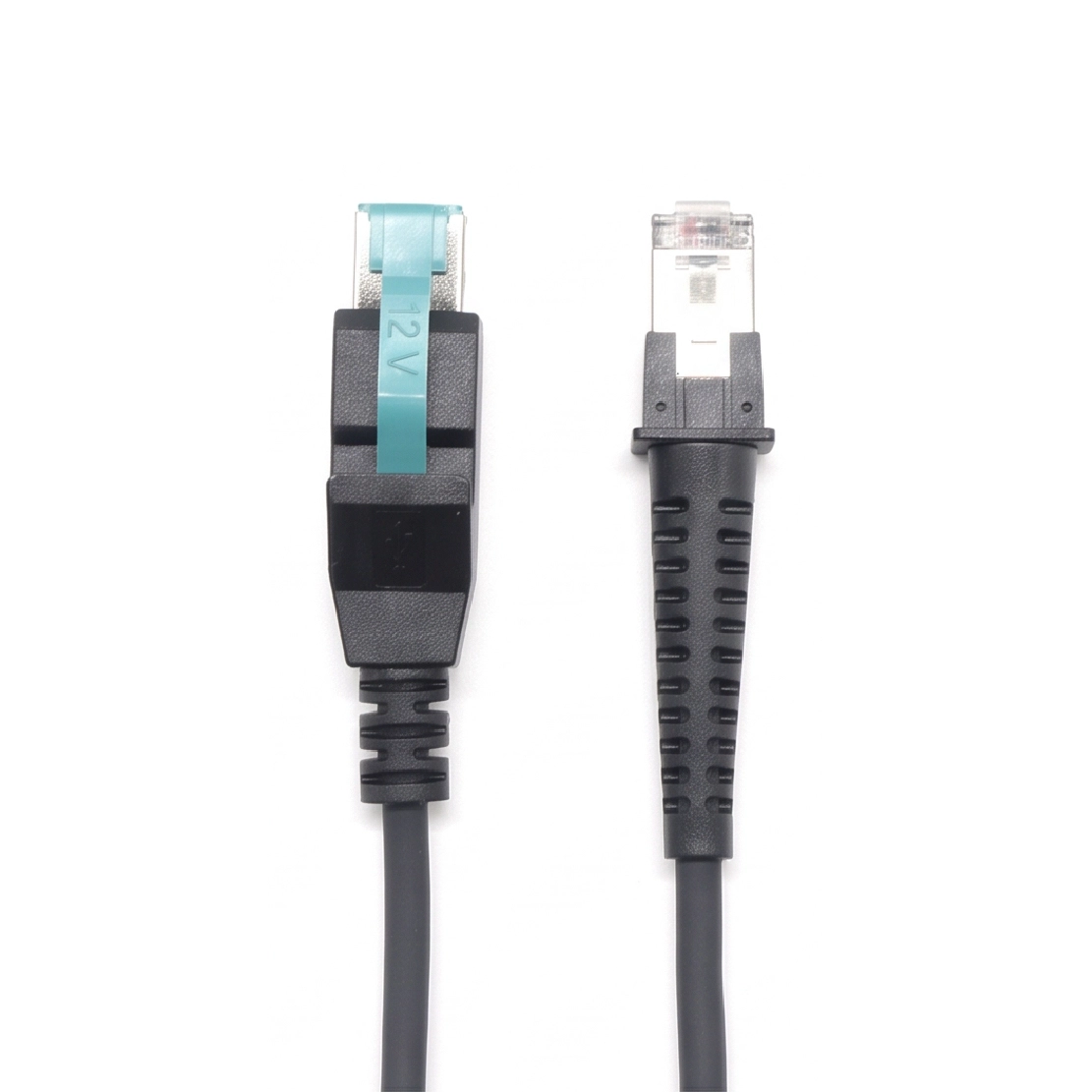
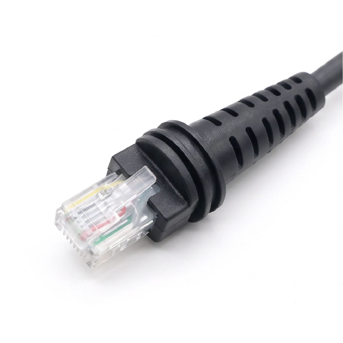
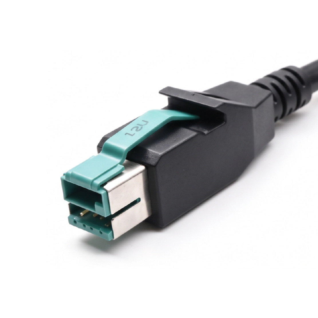
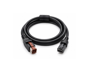
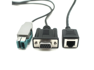
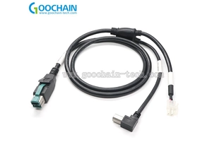
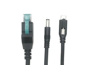
The illustrated configuration has a 12V-marked POWEREDUSB host plug and a modular scanner connector. The exact device-side housing, pinout and electrical functions are defined for the target scanner. Within our POWEREDUSB POS Equipment Cable range, this coiled format addresses moving equipment and the space available for cable storage between scans.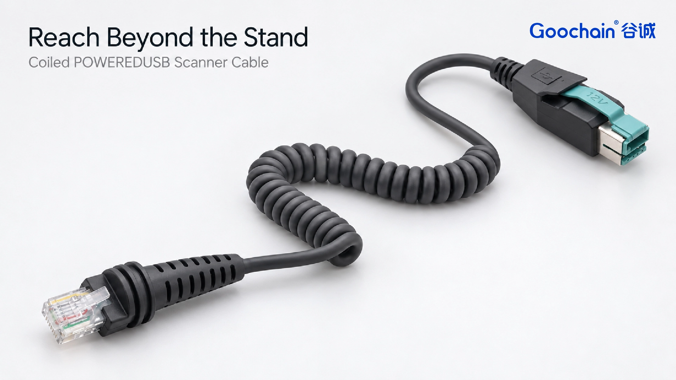
At a checkout or packing station, the scanner may need to reach a carton beside the counter and then return to its stand. Specify that normal movement before choosing the coil. A cable can reach a distant point yet still create too much return force for comfortable handling or pull against the scanner socket.
The drawing should distinguish resting dimensions from operating reach. Measurement reference points and conditions matter: a packed cable bundle, a relaxed assembly and an extended cable describe different states.
| Dimension to define | Why it matters |
|---|---|
| Relaxed overall length | Defines the assembly in its agreed resting state, measured from stated connector reference points. |
| Normal working reach | Covers the intended scanning movement with acceptable pull on the scanner and its connection. |
| Two straight-tail lengths | Locates the coil relative to the host and scanner; each tail is specified separately. |
| Coil geometry | Records coil diameter, pitch and turns for the intended resting space and extension behavior. |
Working reach is not maximum stretch. The greatest distance a coil can be pulled is not a recommended operating distance. Evaluate the sample over the normal scanning path, including its return toward the resting position.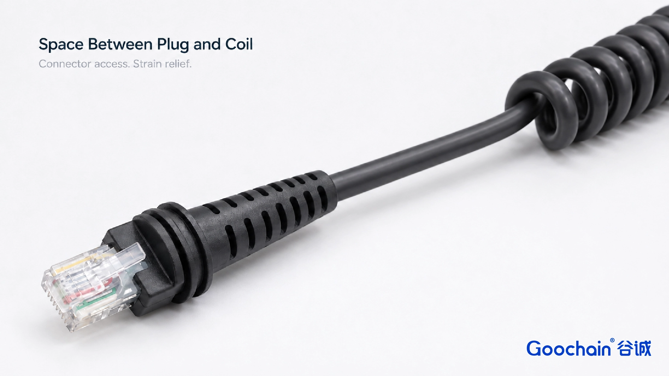
The host-side tail routes the cable away from the terminal before the coil begins. The scanner-side tail provides space for the plug, strain relief and cable bend near the handle or stand. These tails need not be equal: their lengths should reflect the port positions, counter edge and scanner movement.
Position the resting coil where it can extend without catching on the stand, a drawer or nearby equipment. Keep access to connector releases and avoid supporting the cable by a tight bend immediately behind a plug. Review the movement through the full normal scan area, not just one extended position.
For a fixed scanner with spare length secured along a defined route, a straight cable may be more suitable. Where the equipment specifies that interface, our 12V POWEREDUSB to RJ50 10P10C Scanner Cable offers a separate straight-cable configuration; connector fit and wiring still require model-specific review.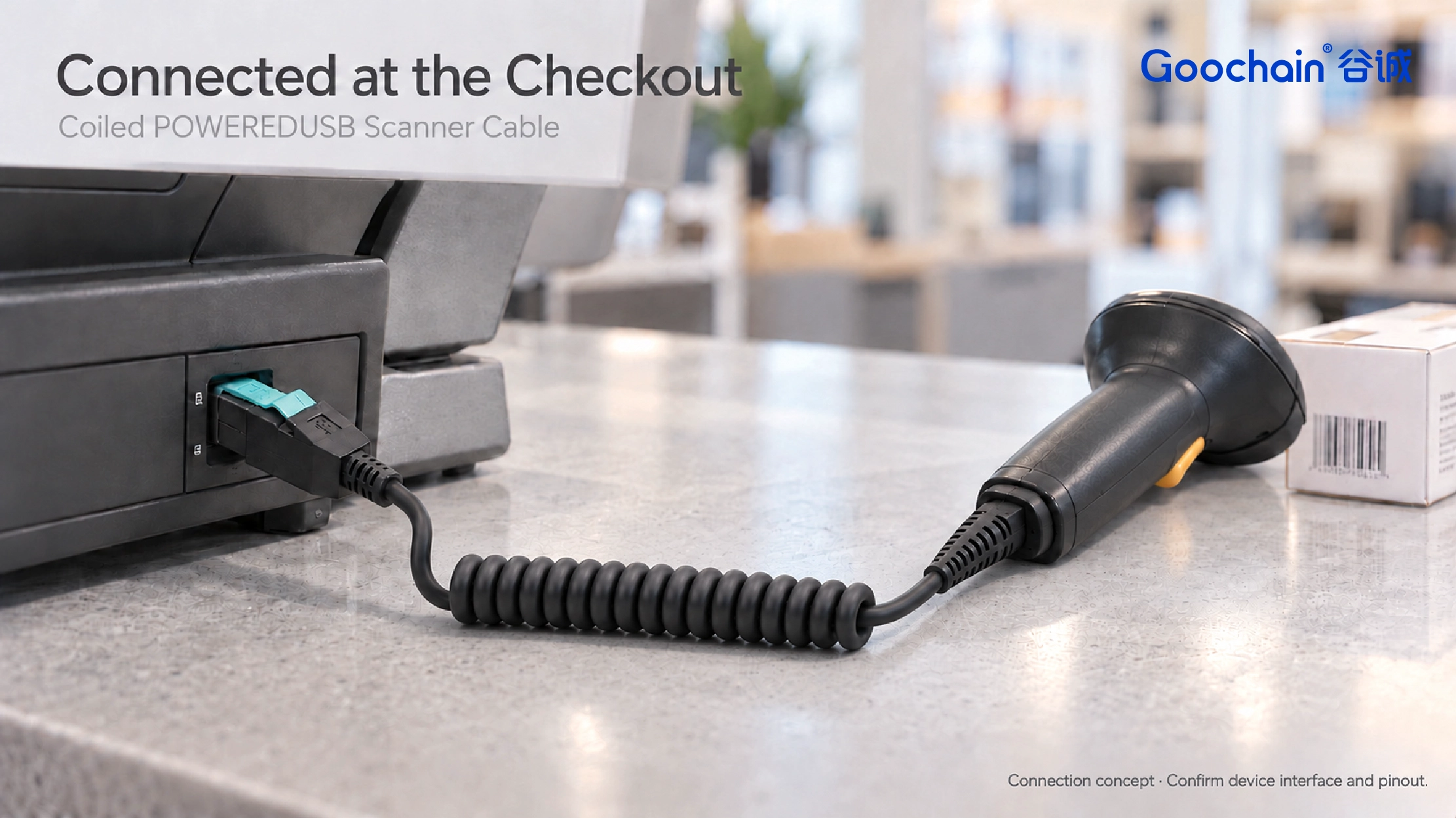
A coiled shape does not determine electrical compatibility. Confirm the POWEREDUSB voltage keying, scanner connector, contact assignment and required power/data functions together. A modular plug that looks similar to the original is not sufficient evidence of a matching interface.
Jacket and conductor selection should reflect repeated movement as well as the electrical requirements. If a project specifies extension or bending life, define the stroke, applied force, bend conditions, cycle rate and acceptance criteria. The finished sample must be evaluated to that method before a cycle-life figure is claimed.
Goochain supports custom powered USB cable development and OEM assembly in Dongguan, China. Sample review brings together connector fit, wiring, usable reach, coil recovery and the load transferred to both plugs. The approved drawing then records the construction and checks required for repeat production.
Our Factory & Quality process covers incoming materials, assembly workmanship and final inspection. Project-specific checks can include dimensions, electrical continuity, appearance, identification and agreed equipment-function testing.
Start with the scanning movement. Send the scanner model, connector photos or mating references, host voltage keying and pin map. Add the normal working reach, preferred relaxed length, both straight-tail lengths, resting space for the coil and target quantity. A reference cable or workstation photo helps define the sample.
Keep required fields minimal. Attach drawings/photos for accurate quoting.
Tip: A simple installation photo often saves 2–3 rounds of questions.
Quotation 1–2 days; development 15–20 days; mass production 20–25 days (project dependent).
Yes. Reference sample + requirements helps confirm drawings and test plan.
Depends on materials and complexity. We support prototypes and scalable mass production.


 English
 简体中文
简体中文  Deutsche
  Italian
  français
  Español
  Nederlands
  日本語
日本語  한국어
한국어  عربى
عربى  português
  Türk
Türk