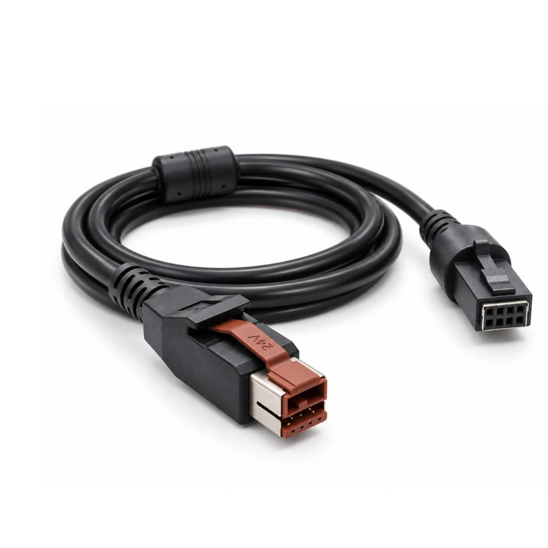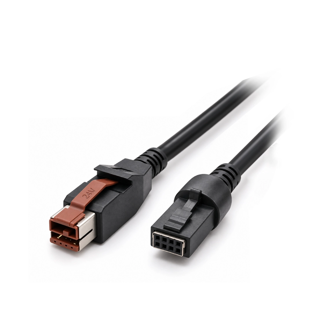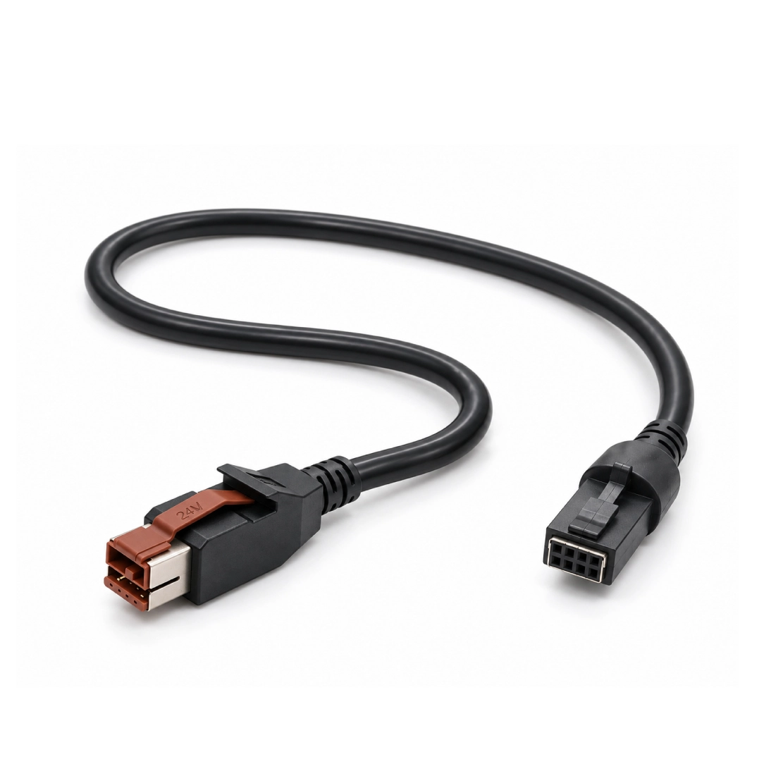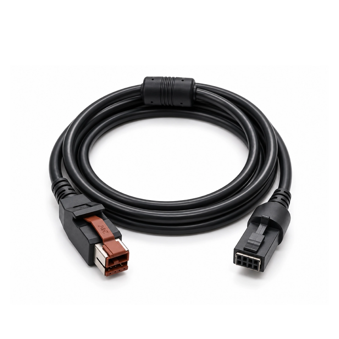


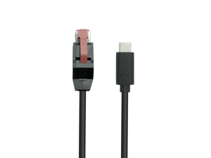
A keyed 24V connection with a two-row device end, specified around the equipment's pinout, operating load and installed cable length.
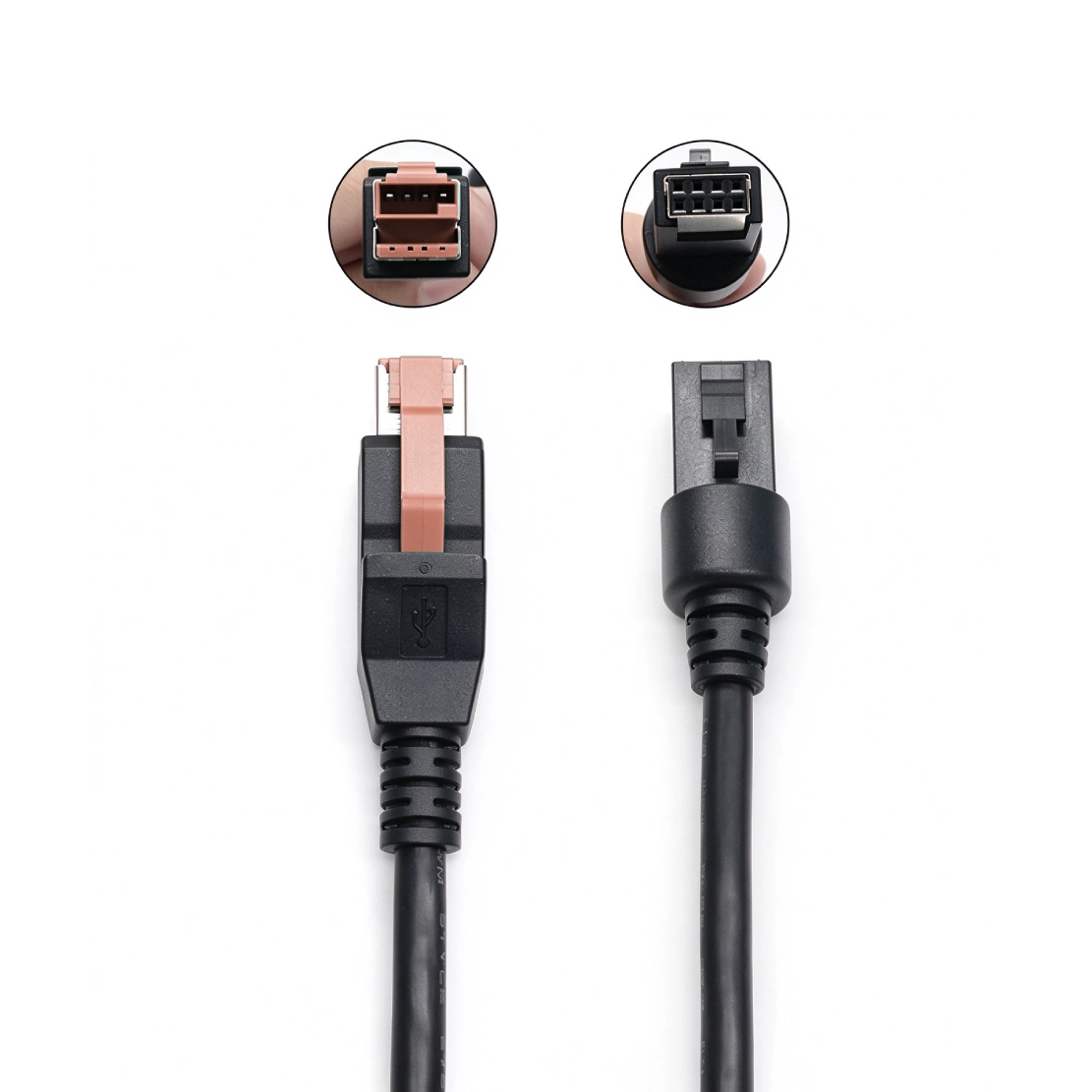
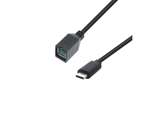
A plug that fits is only part of a 24V cable specification. Goochain builds this POWEREDUSB to 2x4 pin assembly around the device connection, operating load and installed route. The device end has eight positions in two rows of four, with keying, latch engagement and wiring matched to the equipment. Conductor selection takes account of cable length, continuous demand and any startup or operating peaks. For OEM production, the approved connector view, pin map and molded exit define the version to be supplied.
The cable route is often decided late in a POS equipment build, after the host and peripheral have found their places. That route matters to the power connection. Goochain's 24V POWEREDUSB to 2x4 Pin Cable is specified around the installed length, device load and mating interface, with a 24V-keyed host connection and a single eight-position device connector arranged in two rows of four.
For a new installation or a replacement assembly, we review the electrical configuration alongside the physical fit. The result is a defined cable build that your engineering and purchasing teams can identify and order again.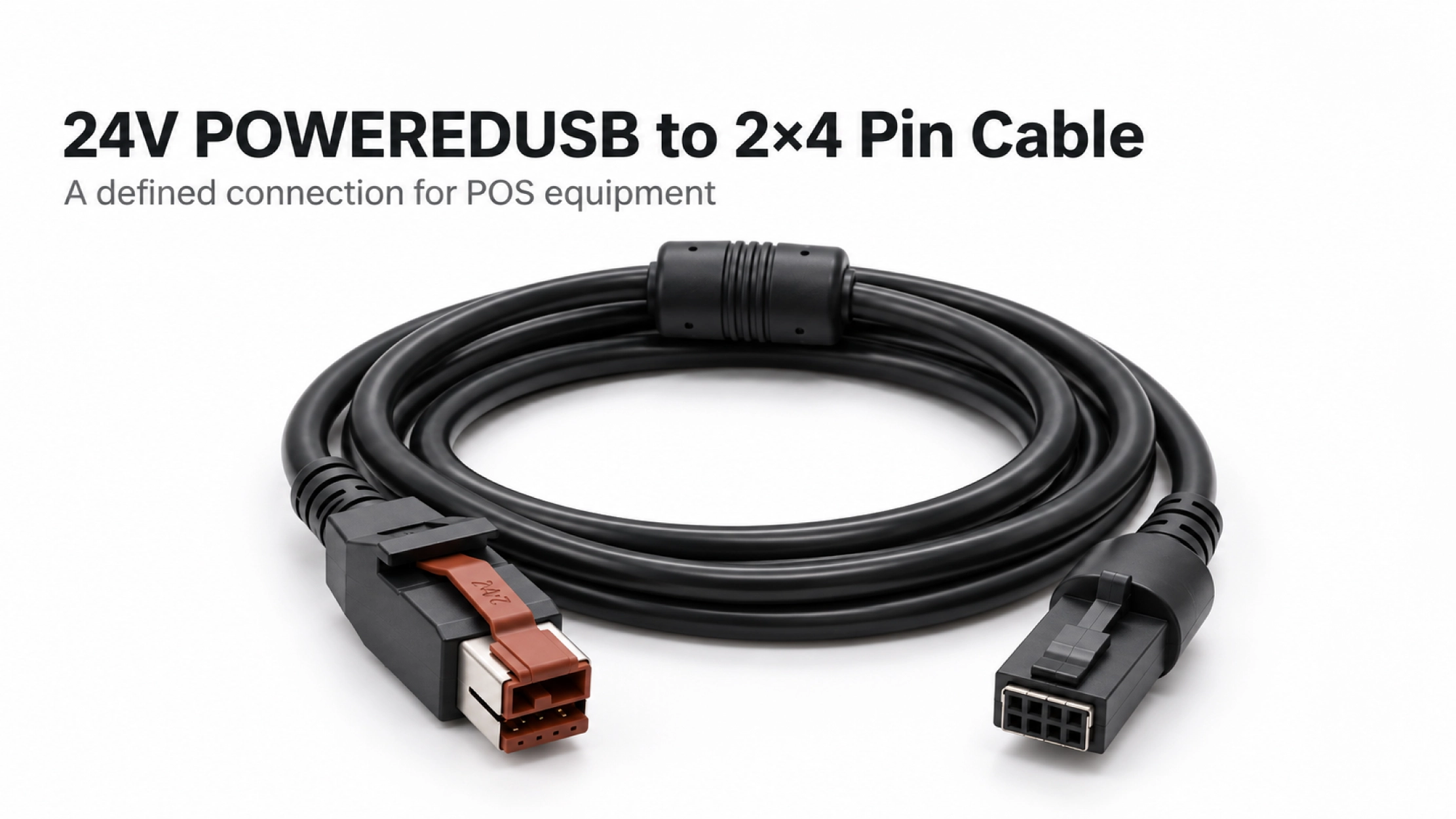
A device's idle demand may tell only part of the story. Startup or operating peaks can place different demands on the connection. Before choosing the conductors, we ask for the continuous load, any relevant peaks and the voltage range the peripheral accepts at its input.
Those requirements are considered with cable length and the selected contacts. If the device moves farther from the host, the original wire gauge should be reviewed rather than carried over automatically. The 24V designation identifies the auxiliary supply; the current rating belongs to the specified complete assembly.
| Project Input | What It Helps Define |
|---|---|
| Continuous load and operating peaks | Conductor and contact selection for the intended duty |
| Installed length and permitted voltage drop | Cable construction suited to the complete route |
| Device socket drawing and pin map | The exact 2×4 connector and power / signal assignments |
| USB function and intended equipment | Sample evaluation with the specified host and peripheral |
The two-row layout is a useful description, but it is not a complete connector specification. Key position, contact arrangement and latch engagement must match the equipment. The wiring map then identifies where each required power and signal connection goes.
When a connector part number is unavailable, a clear mating-face photo and a matching sample help us review the interface. The drawing should identify its viewing direction and pin numbering before wiring is approved. For equipment with a different input, the PoweredUSB Cable range provides other connection formats to review.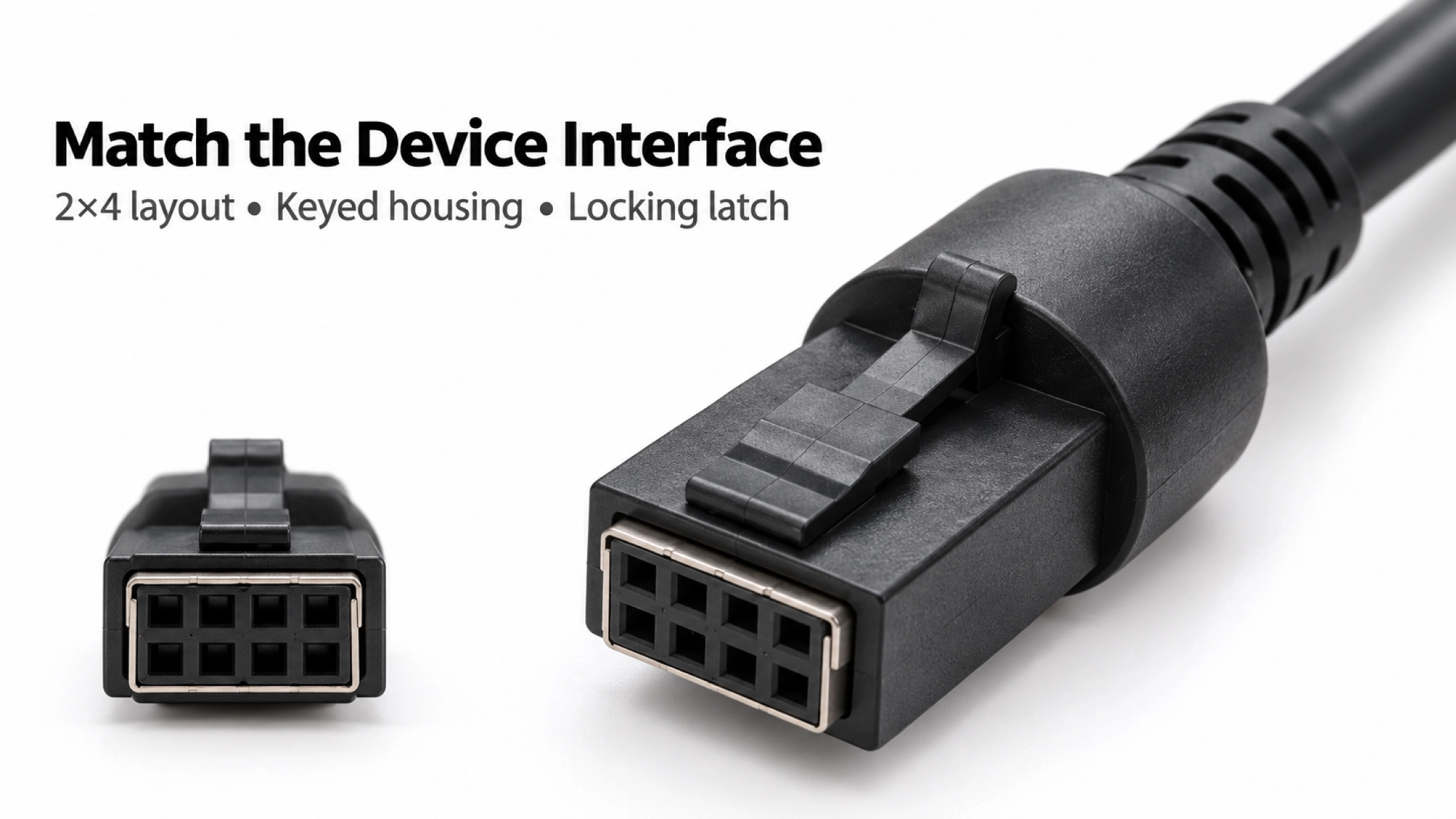
Continuity confirms the intended wire connections. It does not, by itself, establish USB operation or show how the supply behaves under the peripheral's working load. The sample review should therefore reflect the way the equipment will actually be used.
For a data-enabled build, agree the required USB function and evaluate it with the intended host and peripheral. Loaded voltage can be checked at the device input during the relevant operating conditions. These results provide a basis for approving the selected length and construction instead of assigning one performance claim to every custom version.
The overmold and strain relief need room beyond the device socket. A nearby cover, bracket or enclosure wall can force the cable to bend immediately behind the connector. An installation photo helps us assess that space before settling the molded exit.
Goochain can develop the overmold and strain relief around the route, with space for latch access and routine disconnection. The agreed geometry is recorded with the cable construction so a later production batch fits the same equipment layout.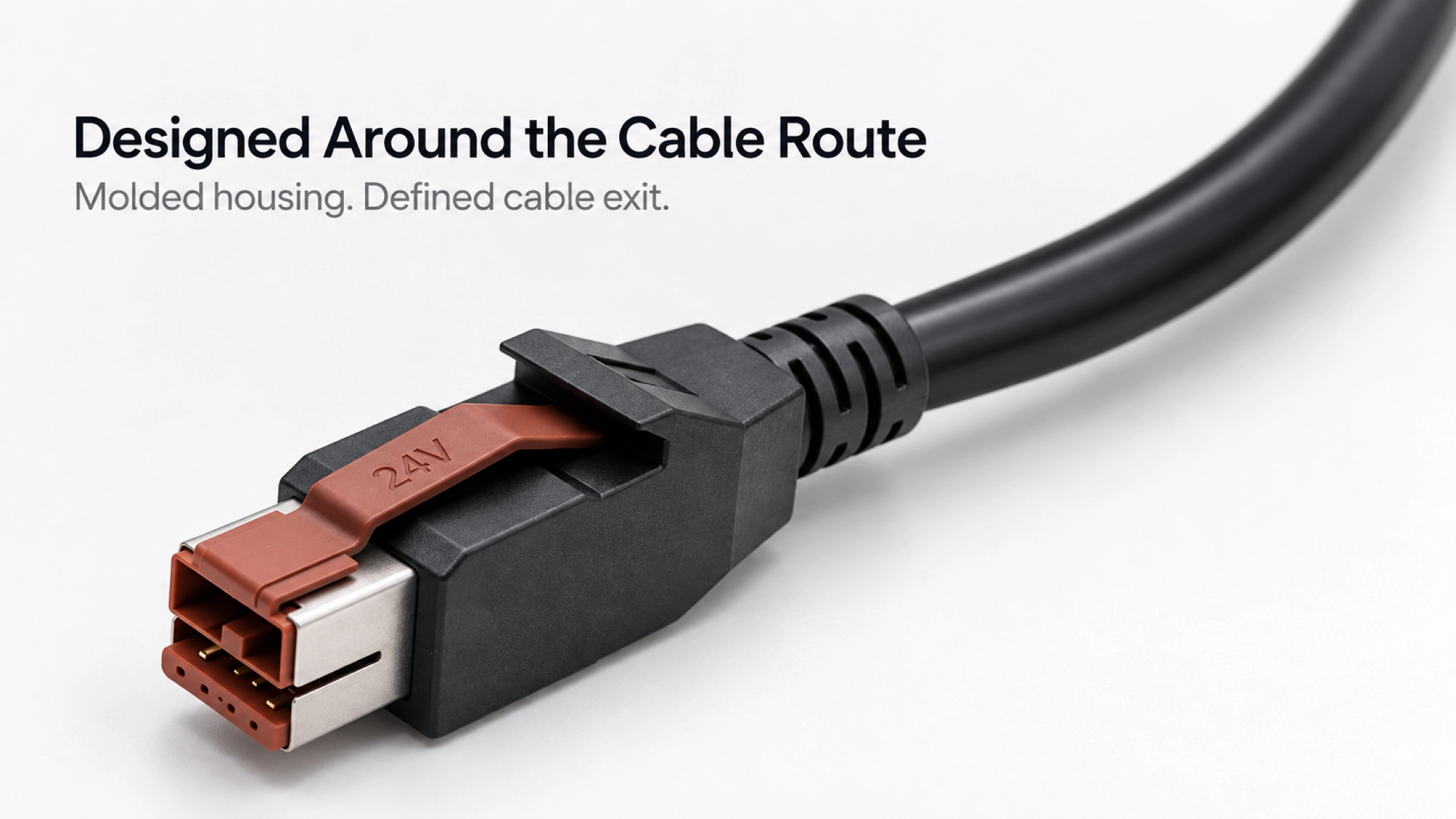
Goochain is a cable assembly manufacturer in Dongguan, China, supporting drawing-based OEM production and ODM development at its 5,000 m² factory. For this powered USB assembly, development can cover connector selection, cable construction, routing and molded structures.
Before production, the approved drawing should bring together the host interface, exact device connector, pin map, length and molded exit. The accepted sample and agreed inspection requirements then define the version to be supplied. Our Factory & Quality overview explains the incoming, in-process and final inspection stages.
Do not assume interchangeability from the two-row device connector. The supply, keying, contacts and pin assignment must match both ends of the intended connection.
That requires a review of the load, permitted voltage drop, contact system and USB requirement. Record the new length with its approved construction rather than treating it as a length-only change.
This is a custom cable series. Electrical ratings are confirmed for the selected complete assembly, including its conductors, contacts and length.
Send the Route and Load with the Connector Details
For a quotation, share the host and device-interface drawings or samples, pin map, installed length and expected quantity. Include the continuous load, any startup or operating peaks and the USB function required. An enclosure photo is useful when space around the device connector is limited.
Keep required fields minimal. Attach drawings/photos for accurate quoting.
Tip: A simple installation photo often saves 2–3 rounds of questions.
Quotation 1–2 days; development 15–20 days; mass production 20–25 days (project dependent).
Yes. Reference sample + requirements helps confirm drawings and test plan.
Depends on materials and complexity. We support prototypes and scalable mass production.


 English
 简体中文
简体中文  Deutsche
  Italian
  français
  Español
  Nederlands
  日本語
日本語  한국어
한국어  عربى
عربى  português
  Türk
Türk