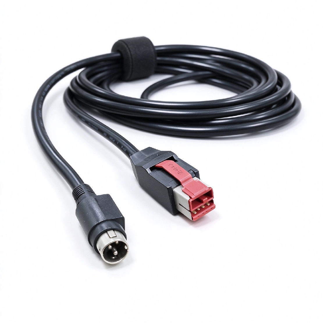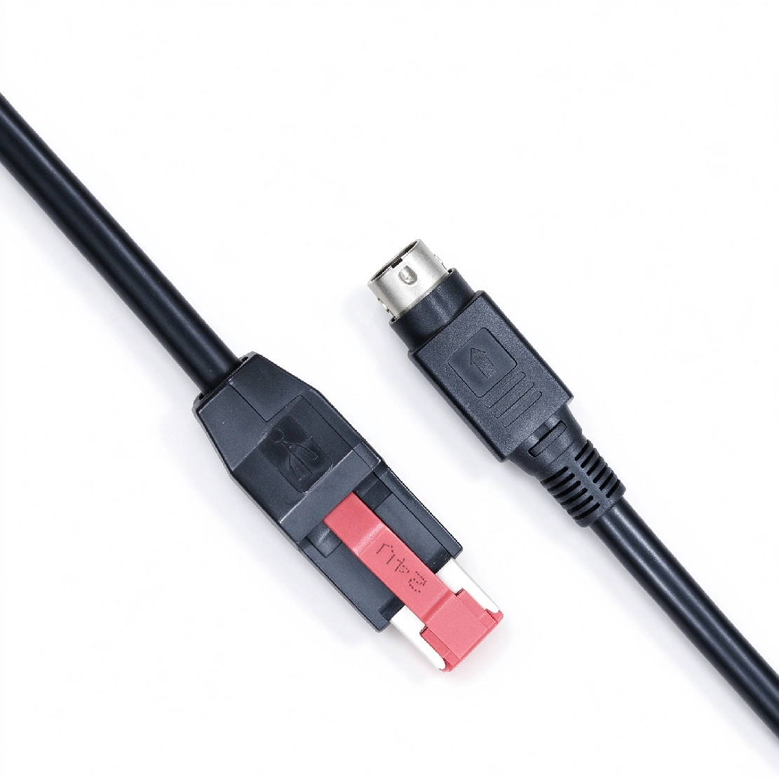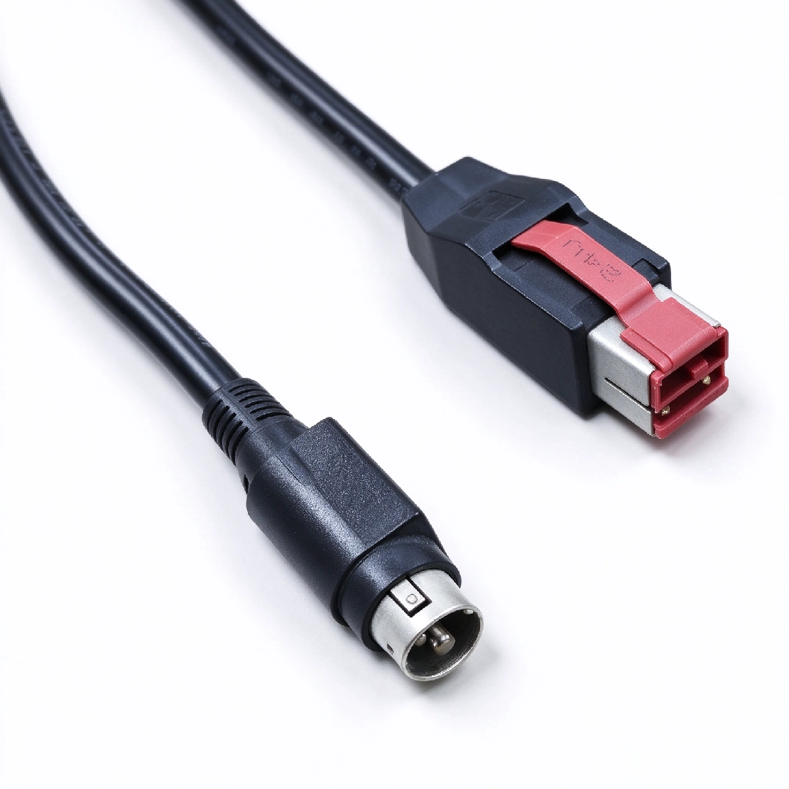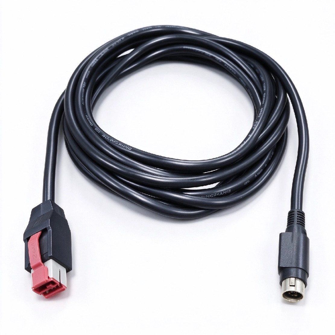



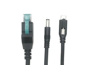
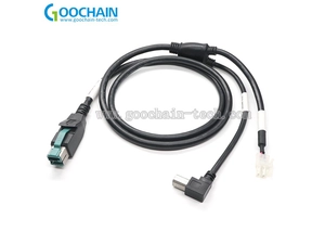
A dedicated power connection for a 24V printer using a matched three-pin socket and a separate communication interface.
When a printer communicates through a separate USB, serial or network connection, its dedicated power socket still needs a correctly matched cable. Goochain manufactures this 24V POWEREDUSB to 3-pin printer power assembly around the actual receptacle and device wiring. The passive build carries the defined host auxiliary supply to the power plug without voltage conversion. Connector series, keying and contact assignment are confirmed together, while cable length and the molded exit follow the space behind the printer. The three-pin device connection is specified for power only.
Goochain manufactures power-only cable assemblies that connect a 24V POWEREDUSB host supply to a printer's dedicated three-pin power input. The device connector and contact assignment are selected for the specific printer interface, with cable length and exit geometry defined for the installation.
This configuration suits compatible POS printers and peripherals in checkout counters or self-service kiosks where communication uses a separate connection. Within our POWEREDUSB cable range, it provides a dedicated power lead without a separate data branch on the cable.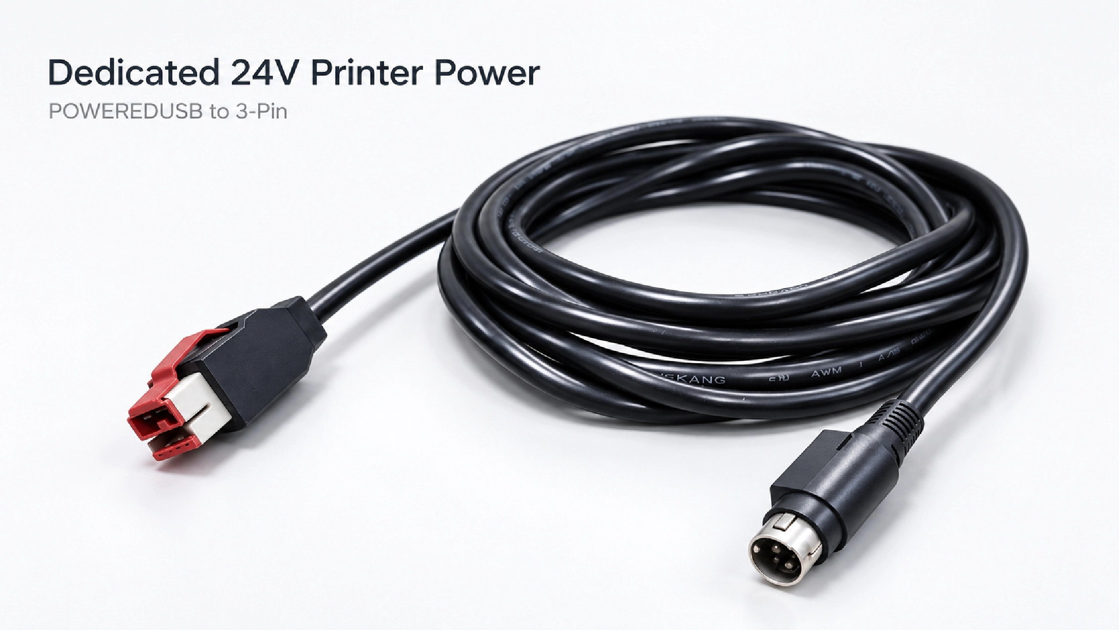
“Three-pin” identifies a contact count, not a universal printer connector. A replacement must match the equipment receptacle mechanically and electrically. Similar-looking housings can use different keying, contact geometry or wiring, so the connector series or mating-part reference should be established before sampling.
| Interface detail | What to confirm |
|---|---|
| Connector system | Exact series, cable-side connector and matching printer receptacle. |
| Mating geometry | Housing profile, keying, contact type and engagement depth. |
| Contact assignment | The role of each position, supply polarity and the drawing's viewing direction. |
| Retention and access | The actual retention mechanism and the space needed to insert and release the plug. |
A connector drawing, mating sample or existing cable helps establish the physical interface. The electrical specification must also define all three contact positions; their functions should not be inferred from the housing shape or contact location. Record whether a pin map is viewed from the mating face or the wire-entry side.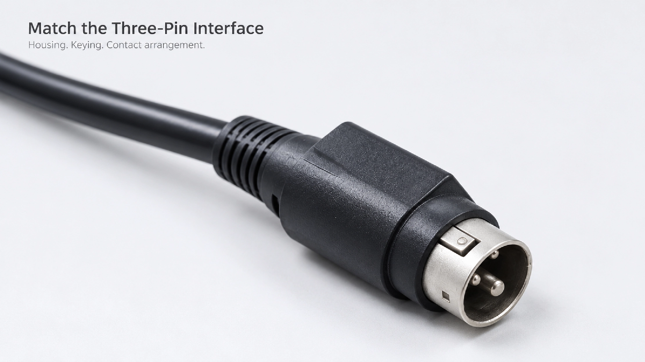
In the passive build, the specified 24V host auxiliary supply is routed to the approved printer power contacts. The host's available output must meet the device requirements, while the cable and connector selection must suit the operating load. Current capability is confirmed for the finished assembly rather than inferred from the three-pin format.
Power only, with no automatic voltage conversion. This cable does not provide USB communication to the printer. It also does not regulate, step up or step down the supply voltage. The source voltage and printer power specification must match.
Where the printer requires a USB-B data branch from the same host connection, review the 24V POWEREDUSB USB-B 3-Pin Printer Y Cable. That configuration has separate data and power branches and requires its own connector and branch-layout review.
The space behind a printer must accommodate the connector body, strain relief and cable bend. For a recessed power socket, check the enclosure opening as well as the connector itself. If the selected plug has a latch, leave access to its release rather than relying on pulling the cable to disconnect it.
Cable length and a straight or angled exit can be developed around the actual route. For an angled version, define the exit direction relative to the connector keying. Include service movement in the layout so the power lead is not held under tension. Conductor selection considers the load, route length and permitted voltage drop.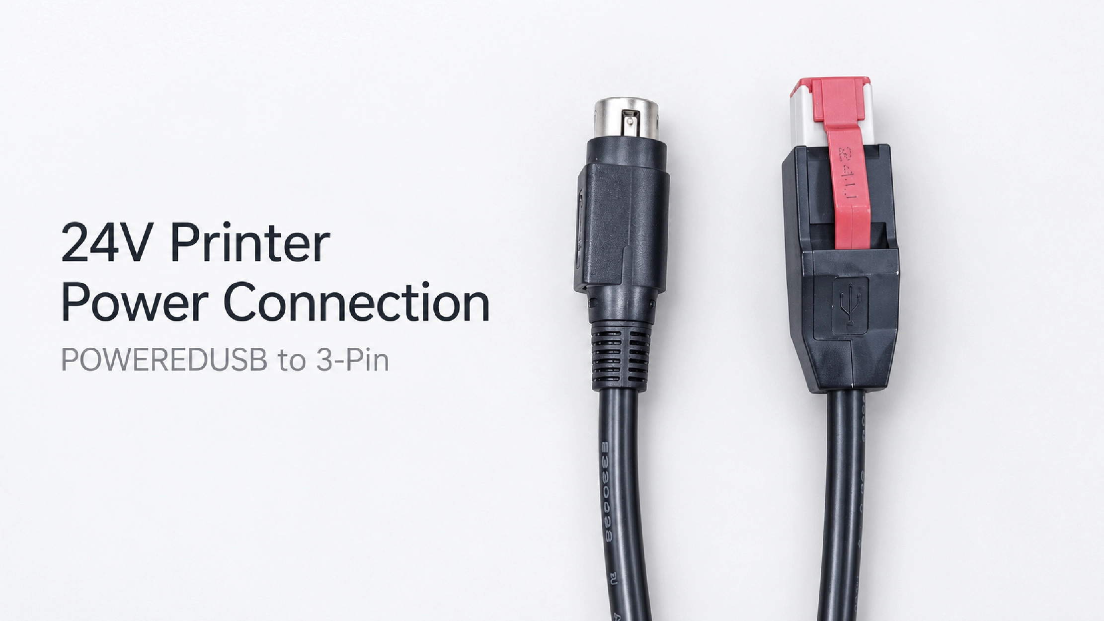
For repeat orders, the approved drawing should record the connector references, contact map, cable length, exit direction and identification. Agreed labels or part numbers can help maintenance teams distinguish similar-looking cable versions; electrical acceptance follows the approved wiring.
Goochain supports OEM production and ODM development of powered USB assemblies at its 5,000 m² facility in Dongguan, China. Our Factory & Quality process supports agreed inspection of connector fit, termination workmanship, continuity, polarity, dimensions and labeling against the accepted specification.
To request a sample or quotation, provide the printer model, three-pin connector reference or mating sample, power specification and contact assignment. Add the required cable length, rear-panel photo, exit-direction constraints and target quantity.
Keep required fields minimal. Attach drawings/photos for accurate quoting.
Tip: A simple installation photo often saves 2–3 rounds of questions.
Quotation 1–2 days; development 15–20 days; mass production 20–25 days (project dependent).
Yes. Reference sample + requirements helps confirm drawings and test plan.
Depends on materials and complexity. We support prototypes and scalable mass production.


 English
 简体中文
简体中文  Deutsche
  Italian
  français
  Español
  Nederlands
  日本語
日本語  한국어
한국어  عربى
عربى  português
  Türk
Türk