


A PoweredUSB cable can pass a continuity test and still deliver too little voltage at the device under load. Cable length, conductor resistance and connector joints all contribute. The USB data path introduces another set of limits that a power calculation alone cannot resolve.
For a simple DC circuit, voltage drop is current multiplied by loop resistance: ΔV = I × Rloop. The loop includes both the supply and return paths. Cable resistance increases with length; conductor size, material and temperature also affect it. Mated contacts add resistance of their own.
Where several contacts or conductors are used, calculate the actual approved circuit arrangement rather than assuming the current divides equally. A connector contact rating is not automatically the rating of the complete cable.
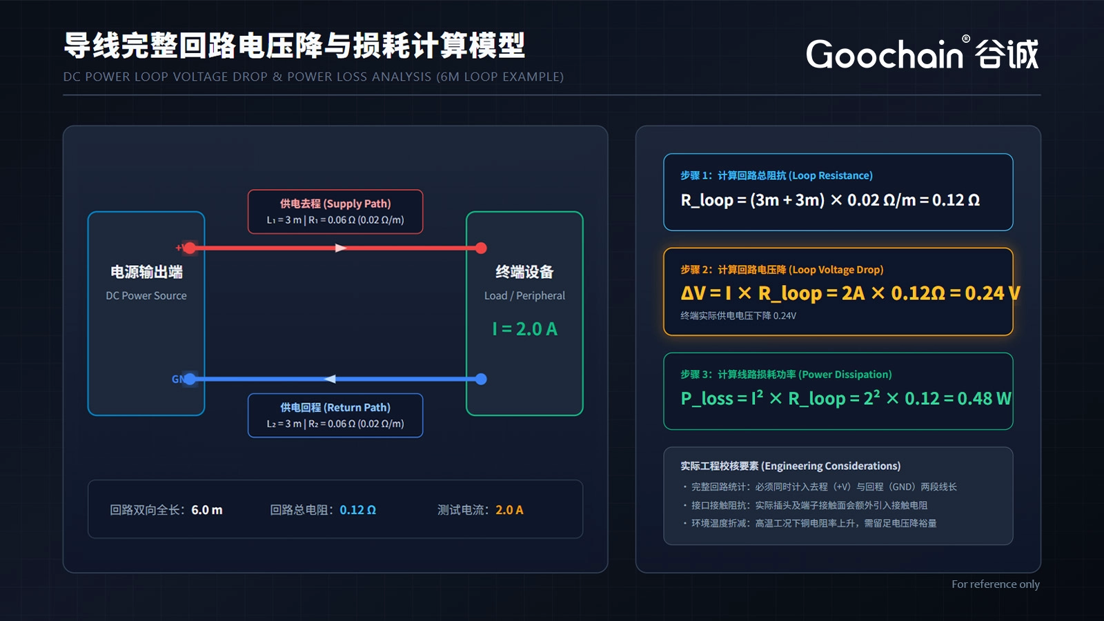
Suppose a design has a 3 m outgoing conductor and a 3 m return conductor. For this example only, assume each has a resistance of 0.02 Ω per meter at the evaluation condition. The wire loop is 6 m × 0.02 Ω/m = 0.12 Ω. At 2 A, the wire-only drop is 0.24 V and its dissipation is 0.48 W.
These are illustrative inputs, not a Goochain cable specification or an AWG rating. Contact losses are excluded. The selected cable material, temperature and actual circuit must be used for a real design. Compare the resulting device voltage against the equipment operating range, including relevant load changes.
| Input | Why it matters |
|---|---|
| Continuous and peak current | Determines drop and heating conditions |
| Supply and return resistance | Defines the complete current loop |
| Total installed length | Includes extensions and branches |
| Contact resistance | Adds loss at each mating interface |
| USB speed and topology | Requires separate signal and system checks |
An extension adds cable and a connector pair. Review the full installed route when selecting a 12V PoweredUSB extension cable or 24V PoweredUSB extension cable. A stable idle measurement does not establish behavior during startup, printing or another peak-load condition.
Using a larger power conductor can reduce resistance, but it also affects cable diameter, flexibility and the overmold. The design has to fit the connector termination and the enclosure.

Power conductors and USB data conductors have different design roles. Meeting a voltage-drop target does not prove data operation at the intended speed or distance. The complete link, including extension joints and breakout sections, should be evaluated with the specified equipment.
Goochain reviews powered USB cable construction for OEM projects at its 5,000 m² Dongguan factory. Send continuous and peak loads, the device voltage limits, the complete cable route and required USB function. This gives the engineering team a basis for conductor selection and sample verification.
It can improve the power path, but USB data performance depends on the signal path and system as well.
No. Length needs to be assessed against power requirements, data function and the complete installation.


 English
 简体中文
 Deutsche
 Italian
 français
 Español
 Nederlands
 日本語
 한국어
 عربى
 português
 Türk


