


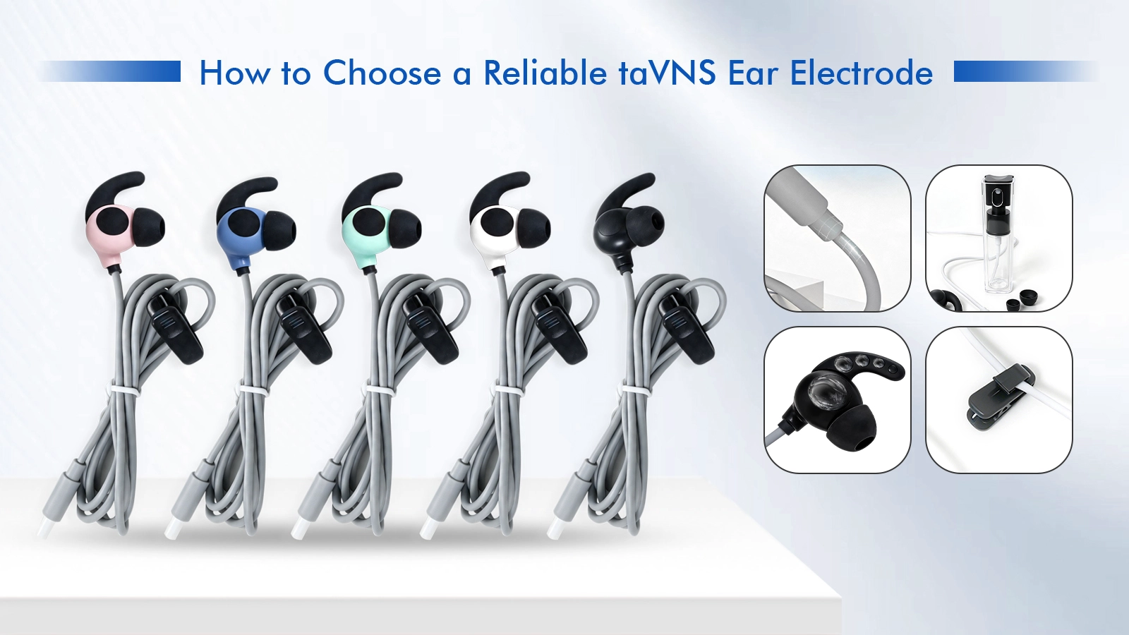
The ear electrode is easy to underestimate. It may look like a small clip or earpiece attached to a cable, but it is the point where electrical, mechanical and user requirements meet. If the component shifts on the ear, applies inconsistent pressure, pulls under cable movement or uses the wrong interface, the device team may see intermittent contact, difficult setup or avoidable support complaints.
For a taVNS or tVNS product team, choosing an electrode should therefore involve more than matching a connector and asking for a low unit price. The right starting point is a clear set of design inputs: where the electrode must sit, how contact is maintained, what electrical interface the device expects, how the cable moves, how the accessory will be cleaned and how the finished component will be validated.
Define the target auricular location before selecting a clip or earpiece form. A tragus-area clip, a concha earpiece and another auricular contact concept create different geometry, retention and cable-routing constraints. The same physical design may not sit consistently across every location or user group.
The use scenario matters as well. A supervised research session, a short home routine and a longer wearable session can create different expectations for setup, pressure, movement and cleaning. Ask who will place the electrode, how often it will be used, whether the user will move during operation and what replacement lifecycle is expected.
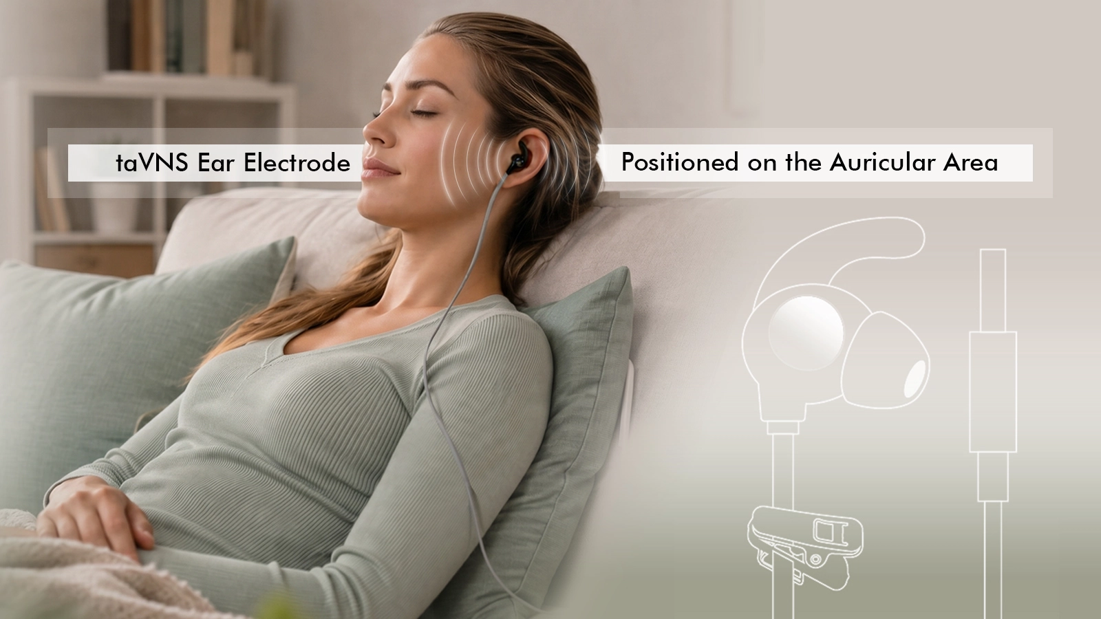
Stable contact does not come from contact material alone. It is the result of electrode geometry, surface area, spacing, contact pressure, ear anatomy, skin condition, cable forces and user placement. A large contact surface may still be unreliable if the clip rotates. A strong clip may resist movement but create excess pressure. A flexible cable may help, but only if the strain relief and exit direction do not load the ear.
|
Factor |
What to Review |
Consequence if Missed |
|
Contact geometry |
Usable area, edge shape, pole spacing and alignment |
Partial or shifting contact |
|
Retention |
Clip force, pressure distribution and resistance to rotation |
Movement or discomfort |
|
Ear variation |
Representative anatomy and placement tolerance |
Works on one user but not the target population |
|
Cable force |
Exit angle, cable weight, routing and user motion |
Electrode is pulled away or twisted |
|
Surface condition |
Cleaning, oils, residue, dryness and wear |
Intermittent contact or inconsistent setup |
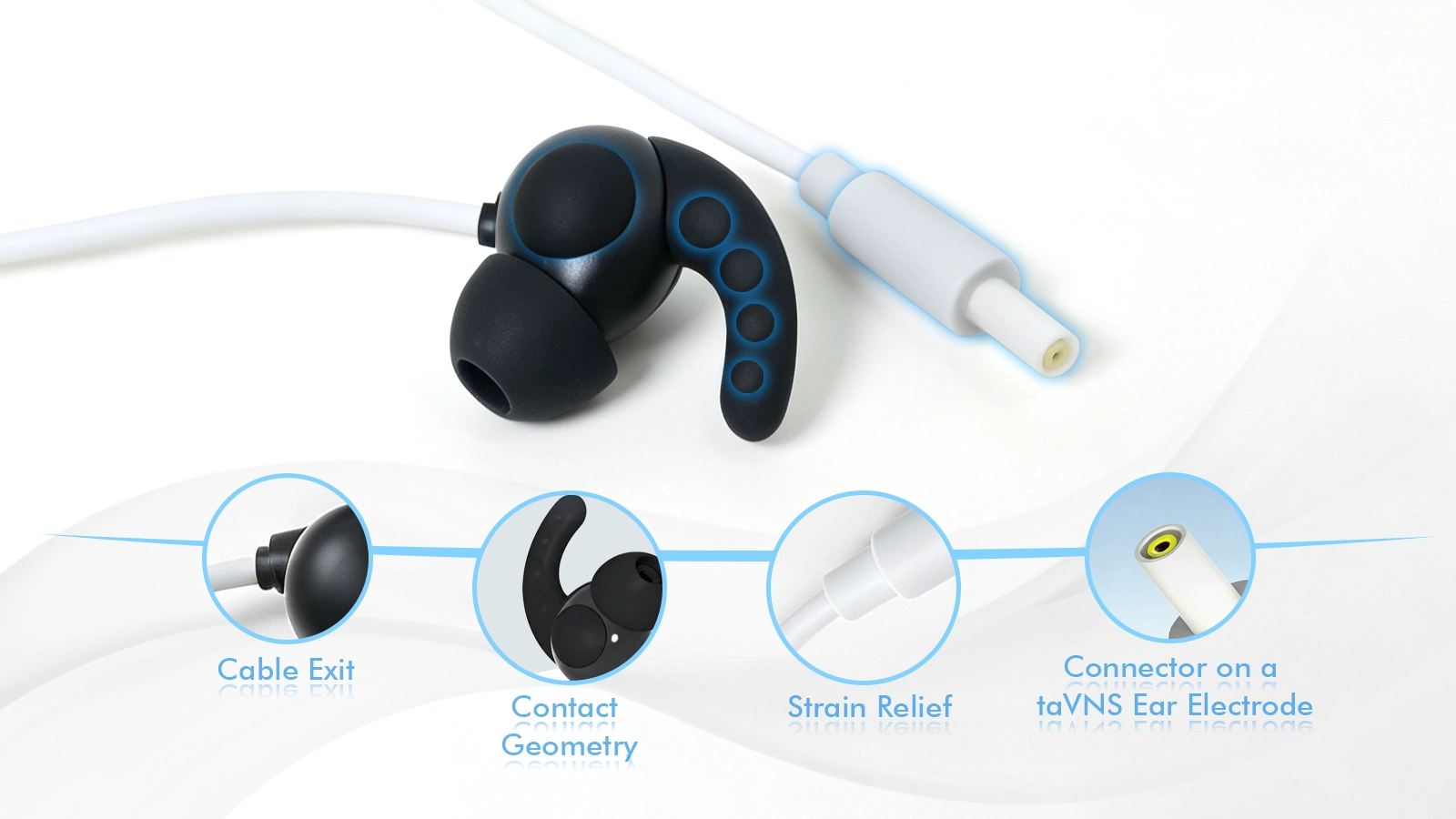
Conductive silicone can combine a compliant skin-facing surface with a molded contact geometry. However, the phrase conductive silicone is not a complete specification. The project should define the approved material, electrical and mechanical characteristics, color, molding process, cleaning exposure and any documentation required for the final device.
Also review how the conductive area is integrated with non-conductive structures and the cable. Gaps, flash, exposed transitions, sharp edges or poor sealing can affect cleanability and long-term handling. The device manufacturer should assess biocompatibility and material suitability for the final intended use and contact duration.
A wearable ear electrode is small; even modest cable movement can create noticeable torque. The conductor construction, cable diameter, jacket flexibility, length, exit direction and strain relief should be chosen together. A soft cable may improve handling but still fail early if repeated bending concentrates at one point.
Define the expected motion and flex-life target. Consider how the user routes the cable, where clothing may catch it, how the device is carried and how the accessory is packed. Representative motion testing is more useful than inspecting a stationary sample alone.
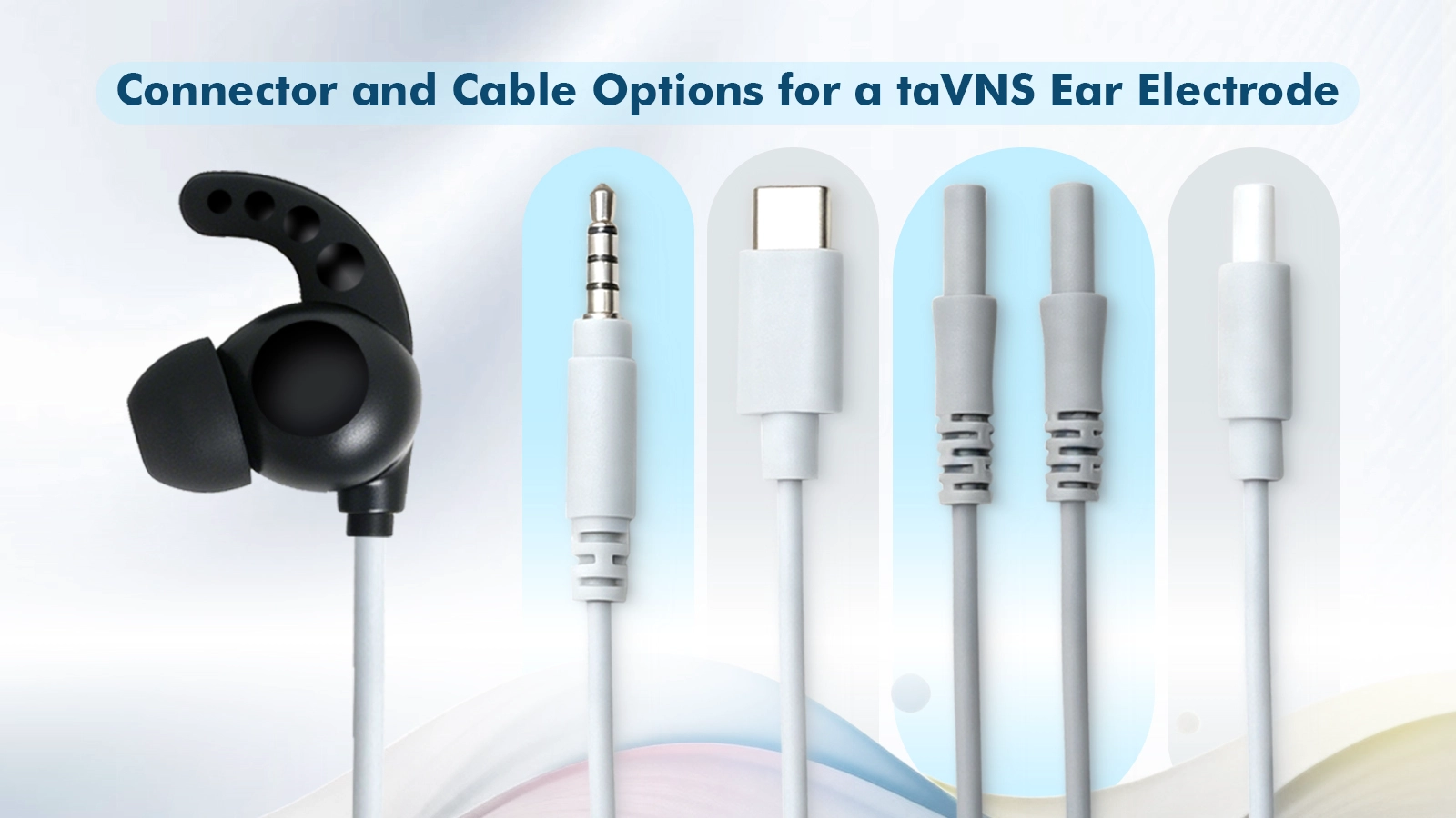
A connector should be specified by more than its diameter or outer shape. The device team should provide the mating interface, pinout, polarity, conductor assignment, output range, insertion and retention expectations, and any labeling or keying requirements.
USB-C requires particular care: using the physical connector does not automatically mean the accessory communicates by USB or is safe to connect to a charger or computer. The mechanical format, electrical assignment and user instructions must all be controlled by the device design.
Reusable electrodes change over time. Contact surfaces can collect skin oils, gel residue or cleaning agents; cable jackets can stiffen or discolor; clips can lose retention; and connectors can accumulate wear. Define what cleaning method is allowed, how the accessory should be dried and stored, and when replacement is recommended.
The correct validation plan depends on the device, intended use, target market and risk analysis. Useful checks may include dimensions, visual workmanship, cable continuity, connector retention, repeated flexing, contact consistency, cleaning exposure, packaging integrity and representative fit evaluation.
Avoid copying a single resistance, impedance, clip-force or cycle limit from another product. A number is meaningful only when the method, sample condition, equipment, anatomy or fixture, environment and acceptance rationale are defined.
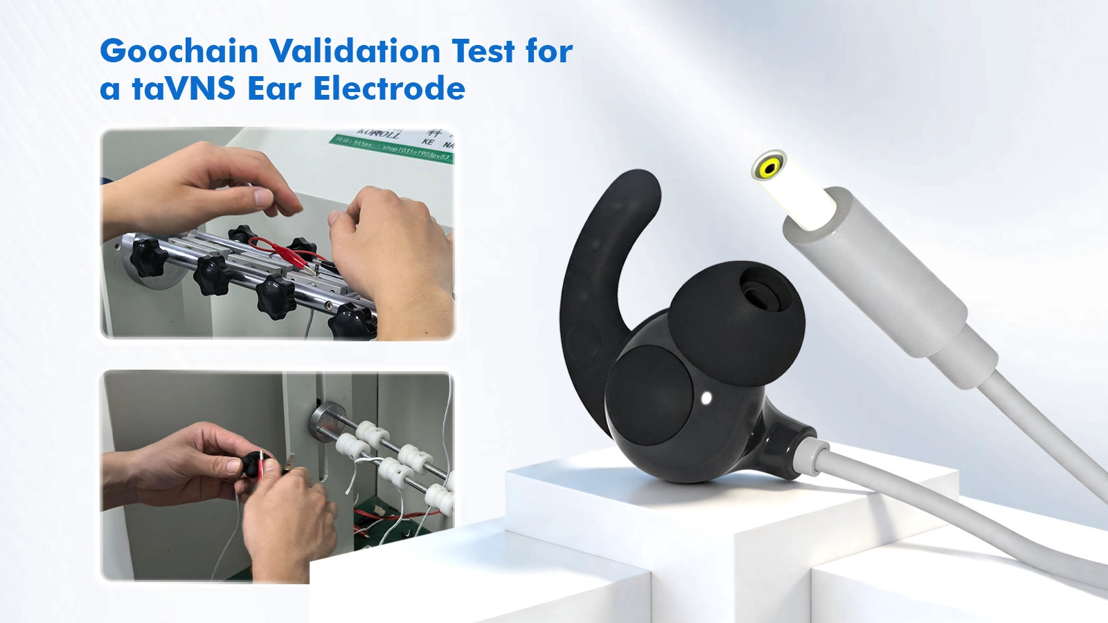
Many suppliers can write OEM or ODM on a web page. A stronger evaluation asks what the supplier can show and control. Request relevant product samples, drawings, process images, material documentation, inspection methods, change-control practices and quality-system scope.
|
Input |
Example Detail |
|
Target position and use |
Tragus, concha or other; wear time; user movement; reusable or limited-use |
|
Mechanical definition |
Envelope, contact arrangement, reference sample, drawing or 3D model |
|
Device interface |
Mating connector, pinout, polarity, output parameters and contact-detection method |
|
Cable requirements |
Length, flexibility, exit direction, routing and flex-life target |
|
Commercial requirements |
Prototype quantity, estimated annual volume, target cost and schedule |
|
Quality and market |
Target market, required documents, packaging, labeling and traceability |
A reliable taVNS ear electrode is not selected by connector size alone. It is engineered around the ear position, contact behavior, user fit, cable mechanics, device interface, cleaning and validation plan. Bringing the electrode supplier into the discussion early can expose mechanical and manufacturing dependencies before they become tooling changes or field complaints.
|
Discuss Your taVNS Ear Electrode Project Share your target ear position, device interface, cable requirements, estimated volume and validation needs. Goochain can review whether an existing configuration or a custom development route is more appropriate. |


 English
 简体中文
简体中文  Deutsche
  Italian
  français
  Español
  Nederlands
  日本語
日本語  한국어
한국어  عربى
عربى  português
  Türk
Türk 

