


A 1×8 connector has eight positions in one row. A 2×4 connector has eight positions arranged in two rows. That difference is easy to see; keying, latch geometry and the device pinout need closer attention before a PoweredUSB cable is ordered.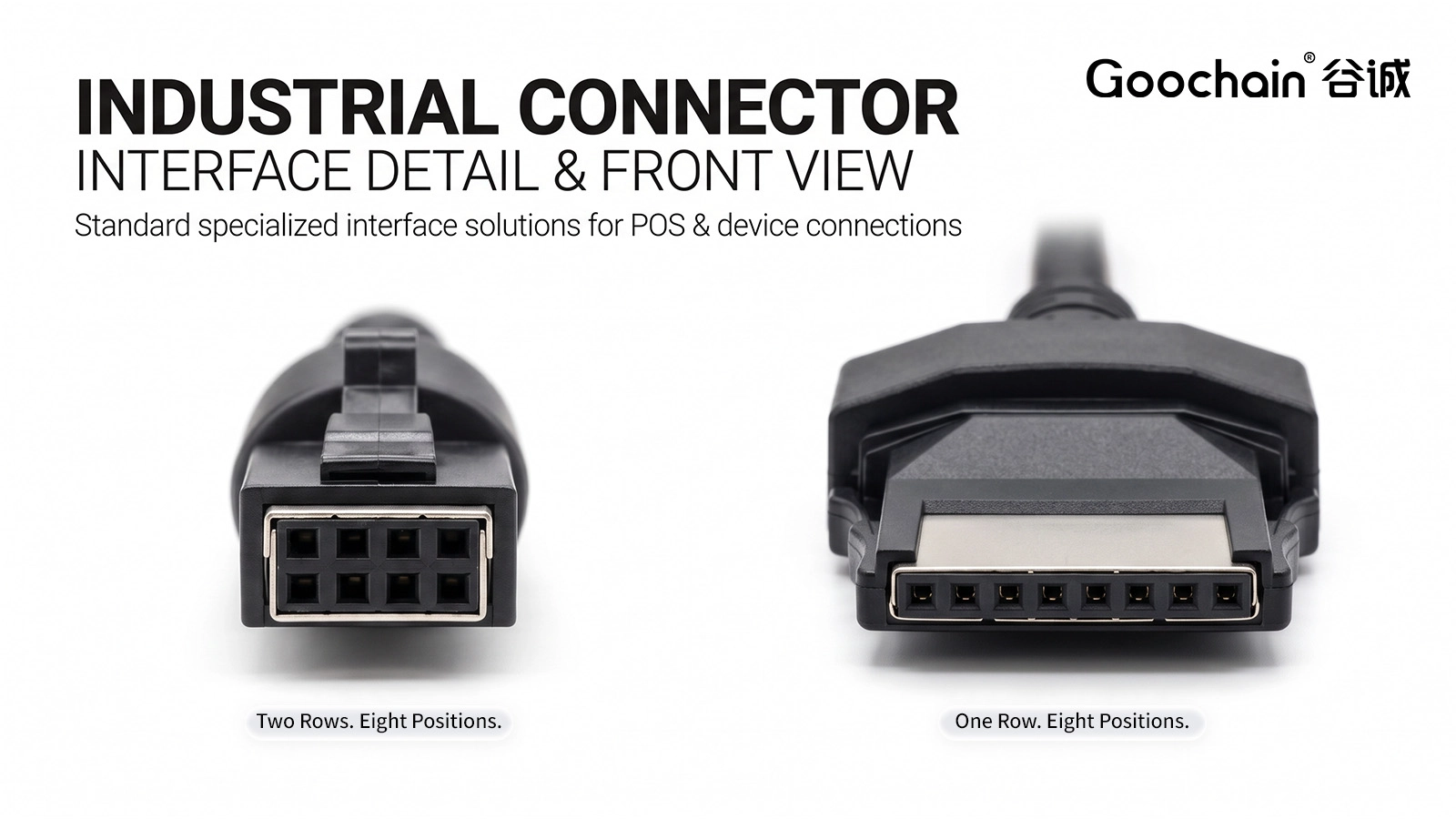
The visible distinction is the contact arrangement: one row of eight versus two rows of four. For selection, specify the manufacturer series or approved drawing, contact arrangement, connector gender and mating part. Housing dimensions and latch design determine whether the plug engages the device socket correctly. A photograph of a cable lying on a table may conceal these features.
For a replacement, photograph the device socket and cable connector directly from their mating faces. Add a side view of the lock. For an OEM design, use the receptacle drawing and tolerances where available; measurements from a loose sample alone are less reliable.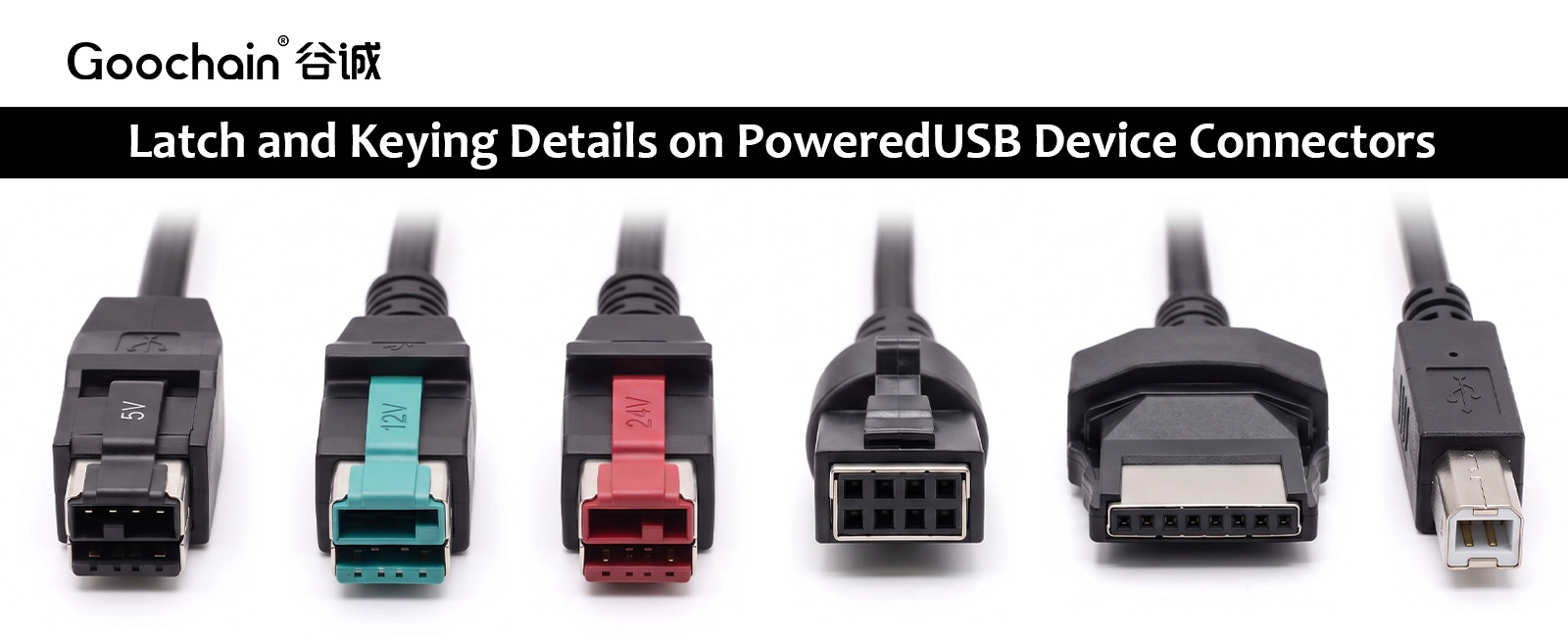
No. The row layout does not replace the electrical specification. A 2×4 device connector may have a keyed variant that must match the intended equipment interface; an ordinary eight-position header should not be treated as an equivalent PoweredUSB connector. The required supply, power-contact assignments and USB connections must be checked against the equipment documentation.
Goochain's 12V PoweredUSB to 2×4 cable and 24V PoweredUSB to 1×8 printer cable are examples of distinct assemblies. Their voltage and device ends describe those particular products; they do not establish a universal rule linking 2×4 to 12V or 1×8 to 24V.
| Check | 1×8 device end | 2×4 device end |
|---|---|---|
| Contact arrangement | One row of eight | Two rows of four |
| Selection basis | Exact connector and device interface | Exact connector, keying and device interface |
| Drawing reference | Pin 1 and viewing direction | Pin 1, viewing direction and key position |
| Interchangeability | Cannot be assumed from pin count | Cannot be assumed from pin count |
State whether the diagram shows the mating face or the wire-entry side. Mark pin 1 and the relevant key or latch so the orientation cannot be reversed when the cable is built. The production continuity-test map should use the same view and contact numbering.
A reference cable can be measured to establish its existing connections, but its wiring should still be checked against the equipment specification. A damaged, modified or unidentified sample is not an authoritative pinout.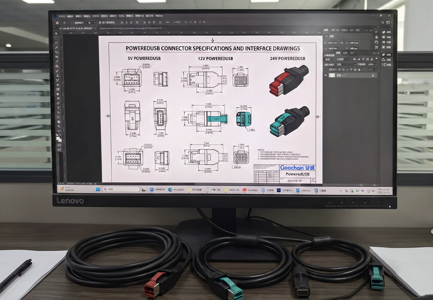
The plug body and strain relief may extend beyond the socket. Measure available space with the connector fully seated, including room to release the latch. If a shallow enclosure calls for an angled exit, specify its direction from a stated viewing position on the drawing.
Goochain supports custom cable layouts and overmold development at its 5,000 m² Dongguan facility. Send the connector-face and side-view photos, equipment model, verified pin map, host voltage and installation dimensions. The resulting sample can then be checked for fit and electrical function against an approved drawing.
Only if the equipment supports the new connector and a redesigned assembly has a verified pin map. The original eight-position count is not enough.
Not simply because it has eight positions. Its contact system, keying, mating geometry and electrical ratings must fit the specific equipment design.
No. Those are examples of specific products in Goochain's range. Confirm the host supply and device specification for the assembly being ordered.


 English
 简体中文
 Deutsche
 Italian
 français
 Español
 Nederlands
 日本語
 한국어
 عربى
 português
 Türk


