


A PoweredUSB cable combines a USB connection with additional power contacts in a defined connector system. For a POS project, the first checks are the host voltage, the device connector and the wiring between them. Cable length and installation details come next.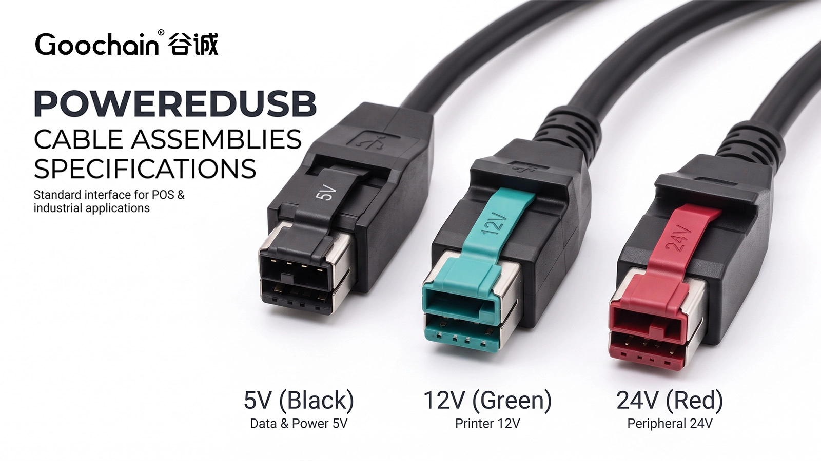
PoweredUSB host interfaces are available in 5V, 12V and 24V versions with corresponding mechanical keying. The voltage identifies the auxiliary supply associated with that interface. It does not mean every contact carries that voltage. The USB portion and the additional power contacts have distinct functions, which must be preserved in the cable design.
Connector color can help identify a version, but the physical keying, equipment documentation and pin map are stronger evidence. A housing color should never be the only basis for selecting a replacement.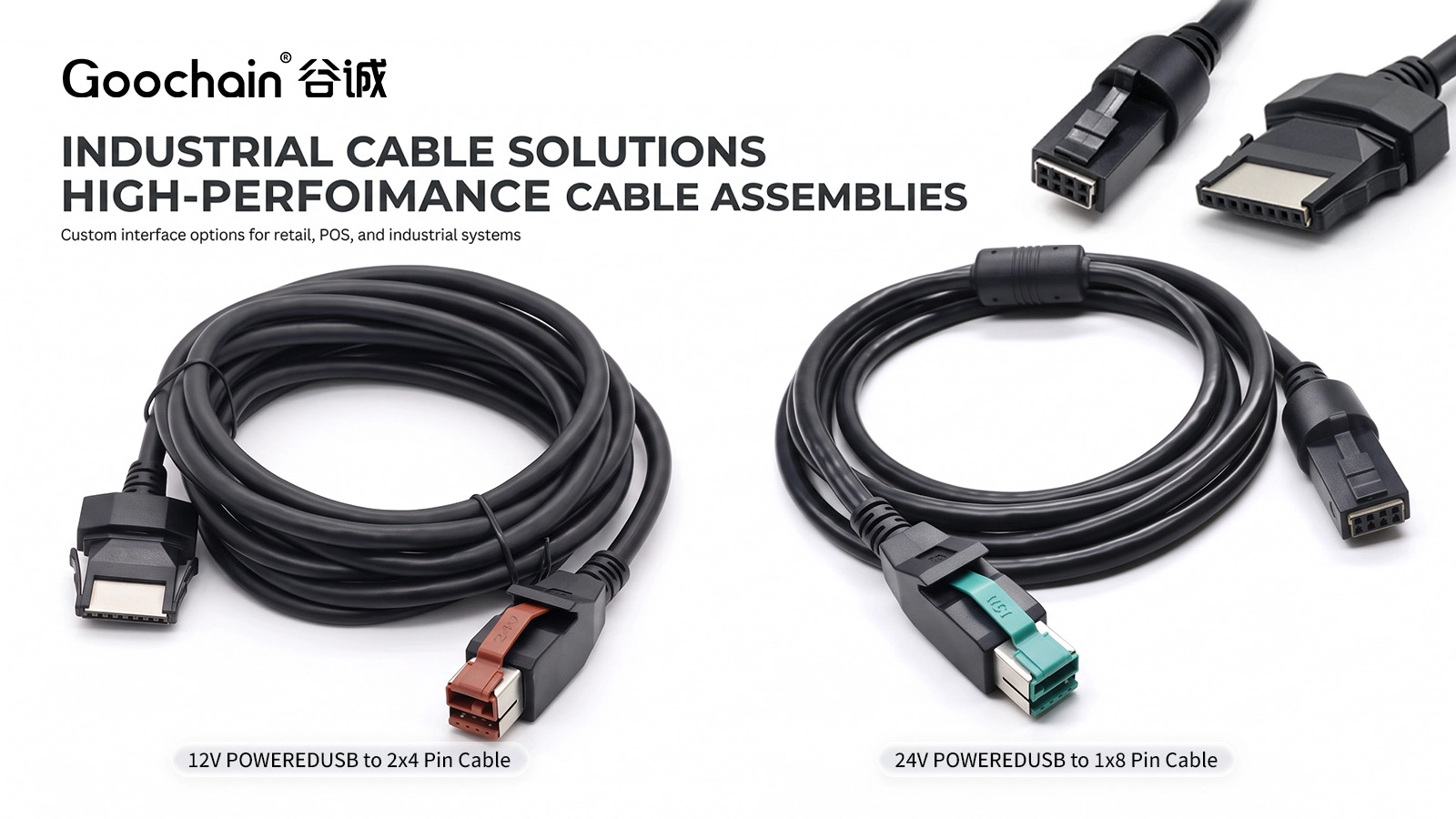
The peripheral may use a 2×4 connector, a 1×8 connector, separate USB-B and power sockets, or a device-specific interface. A host plug that fits correctly does not guarantee the other end is electrically suitable. The PoweredUSB cable range includes these different connection approaches.
For a replacement, collect a clear picture of both connector faces and the equipment model. If the printer or terminal has optional interface boards, identify the board actually installed. Record connector gender, lock features and pin numbering rather than relying on a product photograph alone.
| Check | Information to record |
|---|---|
| Host | Voltage version and keyed interface |
| Device | Connector series, gender, latch and pinout |
| Function | Power only or USB with power |
| Load | Continuous demand and operating peaks |
| Installation | Total length, space and movement |
Some powered USB cable assemblies use the additional supply to feed a DC plug or dedicated power connector. They do not necessarily provide a USB data connection. Other assemblies carry both functions to the device. These configurations need distinct descriptions and part numbers so the purchasing team does not substitute one for the other.
Where a peripheral requires a different voltage, a designed conversion circuit is needed unless the required rail is already available through the specified interface. A passive change of connector is not voltage regulation.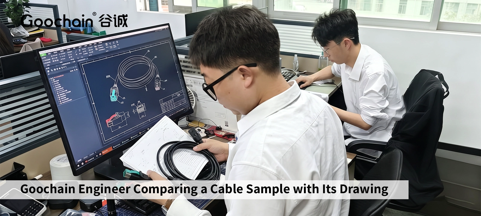
Give the cable manufacturer the host interface, device connector, wiring diagram, operating load and required USB function. Then define the installation length, clearance and any movement. This allows the conductor size, shield and strain relief to be reviewed together.
Goochain manufactures custom PoweredUSB assemblies in a 5,000 m² Dongguan factory. Our OEM and ODM engineering support includes drawing review, sample development and manufacturing planning. Keep the connector reference, cable drawing revision and accepted sample together so a later reorder refers to the same assembly.
The auxiliary supply and USB contacts have distinct assignments. The complete connection must follow the defined interface and cable pinout.
No. The device connector and pin map are also necessary to establish compatibility.


 English
 简体中文
简体中文  Deutsche
  Italian
  français
  Español
  Nederlands
  日本語
日本語  한국어
한국어  عربى
عربى  português
  Türk
Türk 

