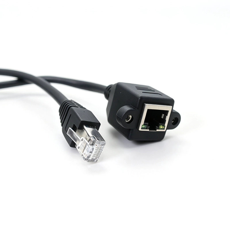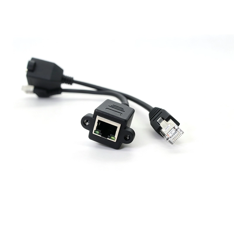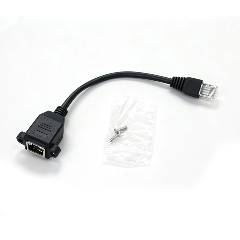


A 5.5mm OD cable with mounting ears and internal magnetics, developed to keep female-side PoE power from reaching the RJ45 male end.
A panel socket is easy to relocate; deciding what reaches the equipment behind it takes more than a straight-through extension. Goochain develops this 200mm RJ45 male-to-female cable with mounting ears, a 5.5mm outer diameter and internal magnetics for a defined PoE-blocking requirement. The female end receives the external network cable and the male end connects to the equipment. The design is intended to retain the specified Ethernet link without delivering female-side PoE DC power to that equipment port. Link speed and blocking performance must be confirmed for the complete build.
An external network connection does not always need to deliver power into the equipment. Goochain's 200mm RJ45 male-to-female panel-mount cable with internal magnetics is developed for installations that need an accessible Ethernet socket and a defined barrier to PoE DC power reaching the male-plug side.
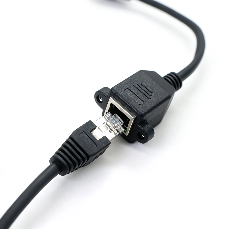
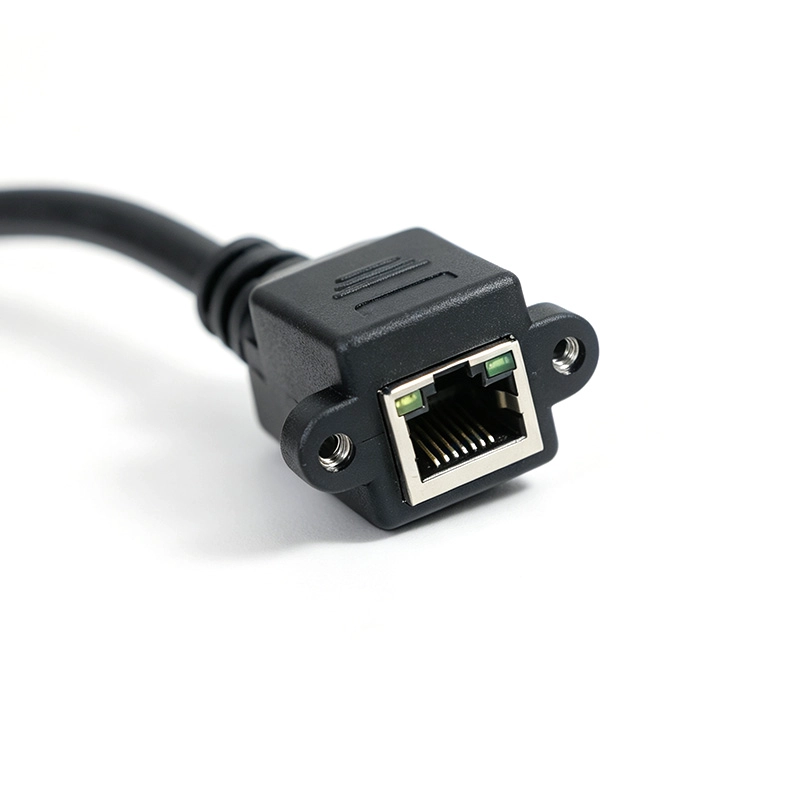
The assembly combines an RJ45 plug, an RJ45 socket, mounting ears and a 5.5mm cable outer diameter. Its internal magnetic circuit is specified around the required Ethernet link and power-blocking arrangement. The intended connection places the female socket at the external network entry and the male plug at the equipment port.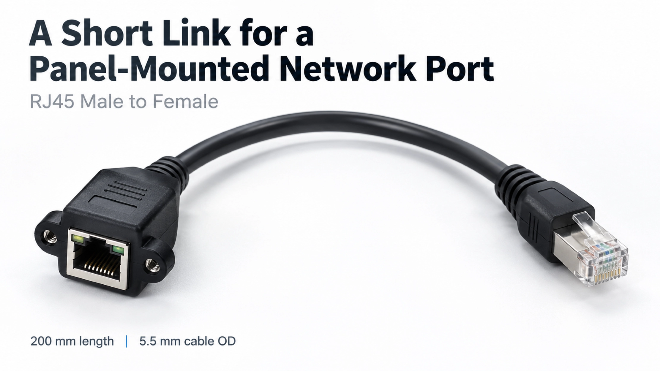
A network port inside a housing can be awkward to reach during installation or servicing. The mounting-ear arrangement provides a fixing point at the panel, while the short male-ended lead connects to the internal equipment port. This keeps the external plug-in point accessible without moving the main board.
The 200mm length suits a short internal route. Check it against the actual socket position, connector body length and space needed for a natural cable bend. Mounting-hole spacing, panel thickness and plug-latch access should be reviewed together before the enclosure cutout is finalized.
For other connector arrangements or routing lengths, our Ethernet Cables range provides a starting point for a custom assembly.
The design requirement is to maintain the specified Ethernet data connection while preventing PoE DC power on the female side from reaching the RJ45 male end. Internal magnetics form part of that circuit; their selection and the complete wiring arrangement determine the result.
PoE blocking must be checked across every relevant conductor path, including any connections that could bypass the magnetic coupling. The supported network speed, power-source type and blocking limits are therefore defined for the approved build and verified on the intended equipment.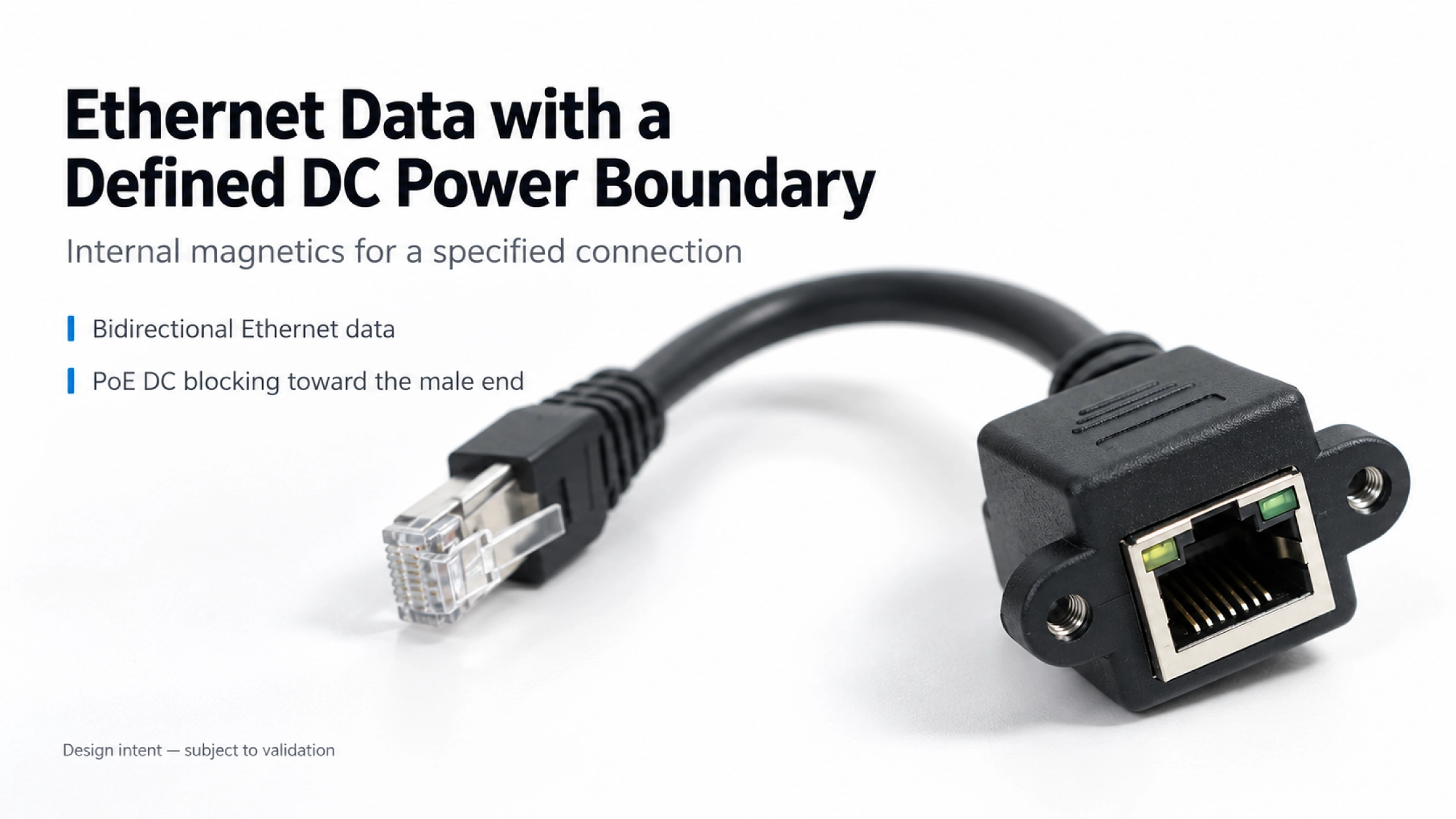
| Connector arrangement | RJ45 male to RJ45 female |
|---|---|
| Specified length | 200mm; measurement points and tolerance per approved drawing |
| Cable outer diameter | 5.5mm |
| Mounting | Mounting ears; fixing dimensions per approved drawing |
| Internal circuit requirement | Integrated magnetic components |
| Power-blocking requirement | Prevent PoE DC power from reaching the male end from the female side, within the validated operating conditions |
| Electrical performance | Ethernet speed, applicable PoE arrangements and isolation ratings to be agreed and validated for the build |
This arrangement can be considered for POS enclosures, kiosks and embedded equipment where the internal Ethernet port should receive data without the specified external PoE supply. The equipment still needs its own intended power source.
For the mechanical review, provide the panel cutout, hole spacing and available depth behind the socket. A photo of the internal route helps establish whether the 200mm lead reaches comfortably and whether a technician can release the RJ45 latch without removing nearby parts.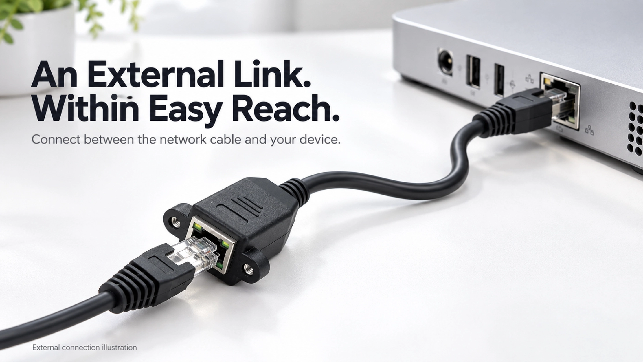
Goochain supports OEM and ODM cable development at its 5,000 m² manufacturing facility in Dongguan. For this assembly, the project starts with two inputs: the enclosure layout and the electrical boundary the cable must provide. Connector selection, magnetic components, wiring, strain relief and identification are then defined in the sample specification.
Sample approval should include data-link operation at the agreed speed and verification of the specified DC blocking under the agreed supply conditions. The accepted circuit, component list and mechanical drawing become the production reference. Our Factory & Quality page outlines the inspection stages used in manufacturing.
The specified design is intended to block PoE DC delivery to that end. Equipment connected there must use its intended separate power source.
Include the required link speed and switch or injector details in the inquiry. Neither the RJ45 connector format nor the 5.5mm cable diameter establishes the supported speed or PoE blocking coverage. Those requirements need to be checked against the complete circuit and sample results.
Yes, custom configurations can be reviewed against your panel drawing and internal route. Specify the length measurement points, fixing dimensions and required cable-exit direction so the sample can be checked in the actual housing.
Send the Panel Drawing and Network Requirement
Include the equipment port details, target Ethernet speed, PoE source and supply arrangement, required blocking limits, panel dimensions and expected quantity. These details allow us to review the magnetic circuit and mounting structure together before preparing a sample.
Keep required fields minimal. Attach drawings/photos for accurate quoting.
Tip: A simple installation photo often saves 2–3 rounds of questions.
Quotation 1–2 days; development 15–20 days; mass production 20–25 days (project dependent).
Yes. Reference sample + requirements helps confirm drawings and test plan.
Depends on materials and complexity. We support prototypes and scalable mass production.


 English
 简体中文
简体中文  Deutsche
  Italian
  français
  Español
  Nederlands
  日本語
日本語  한국어
한국어  عربى
عربى  português
  Türk
Türk