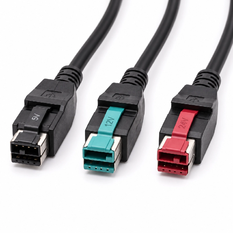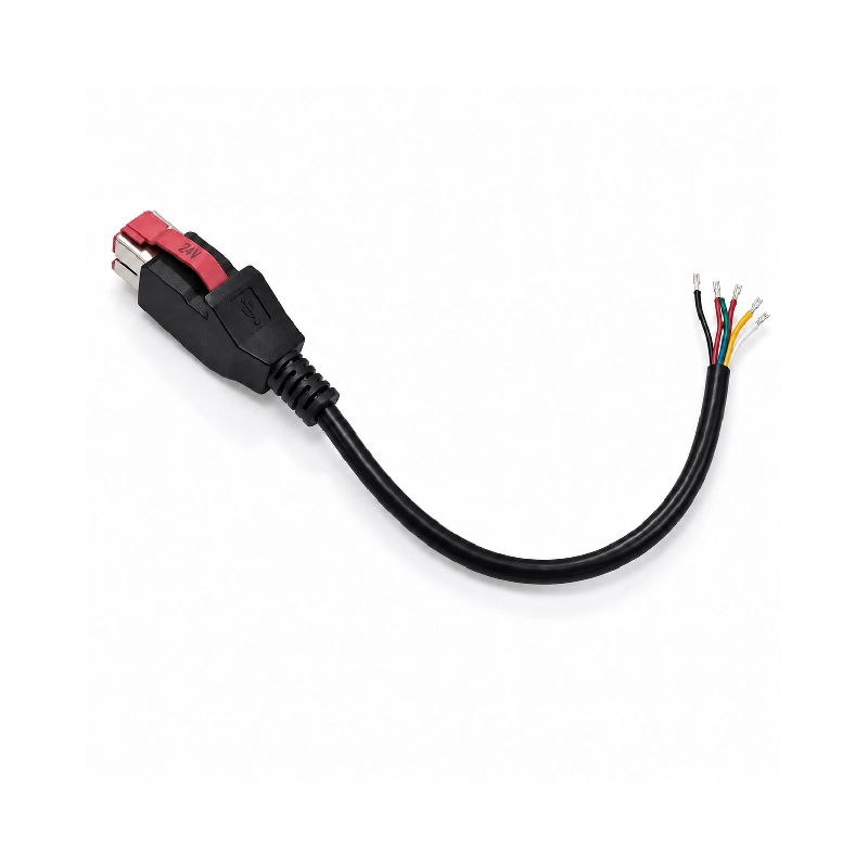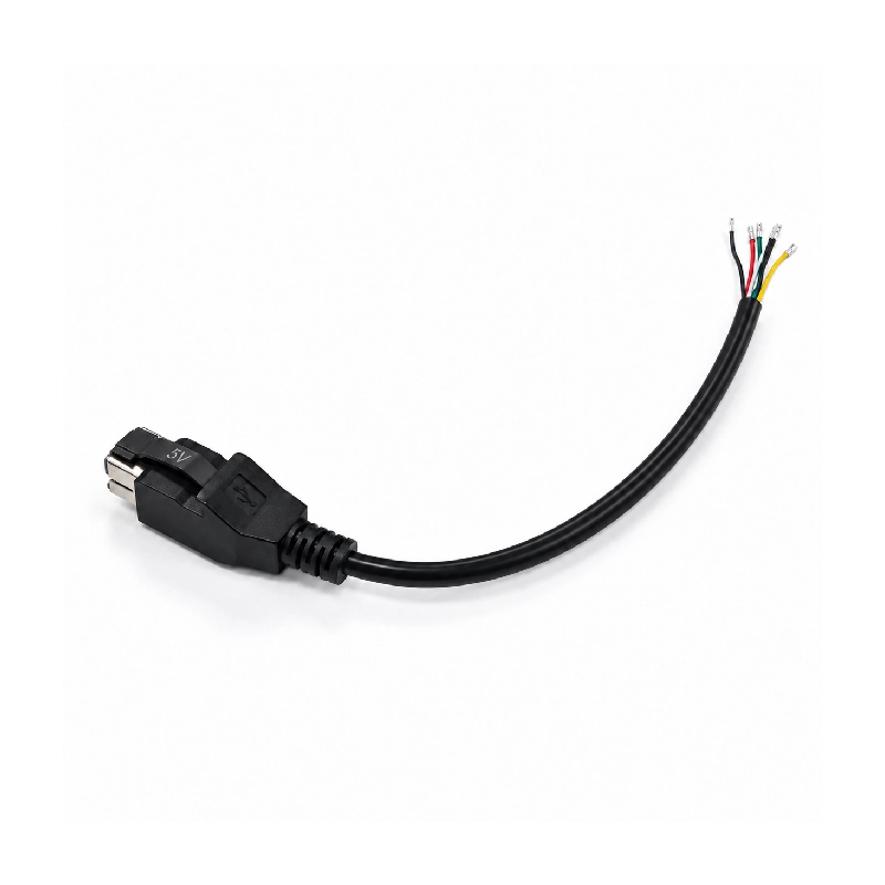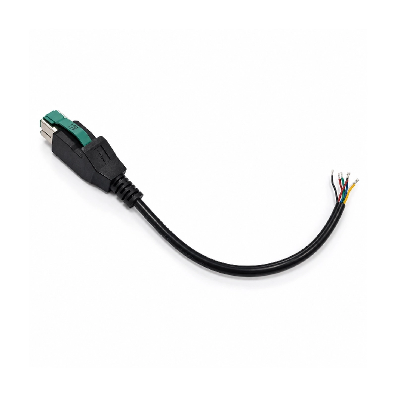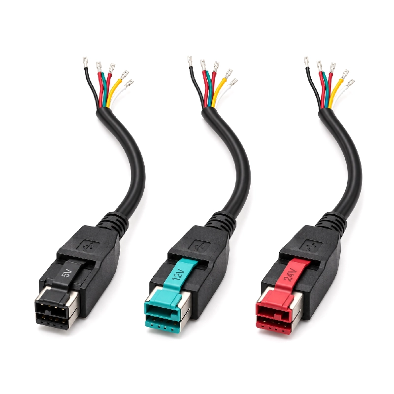


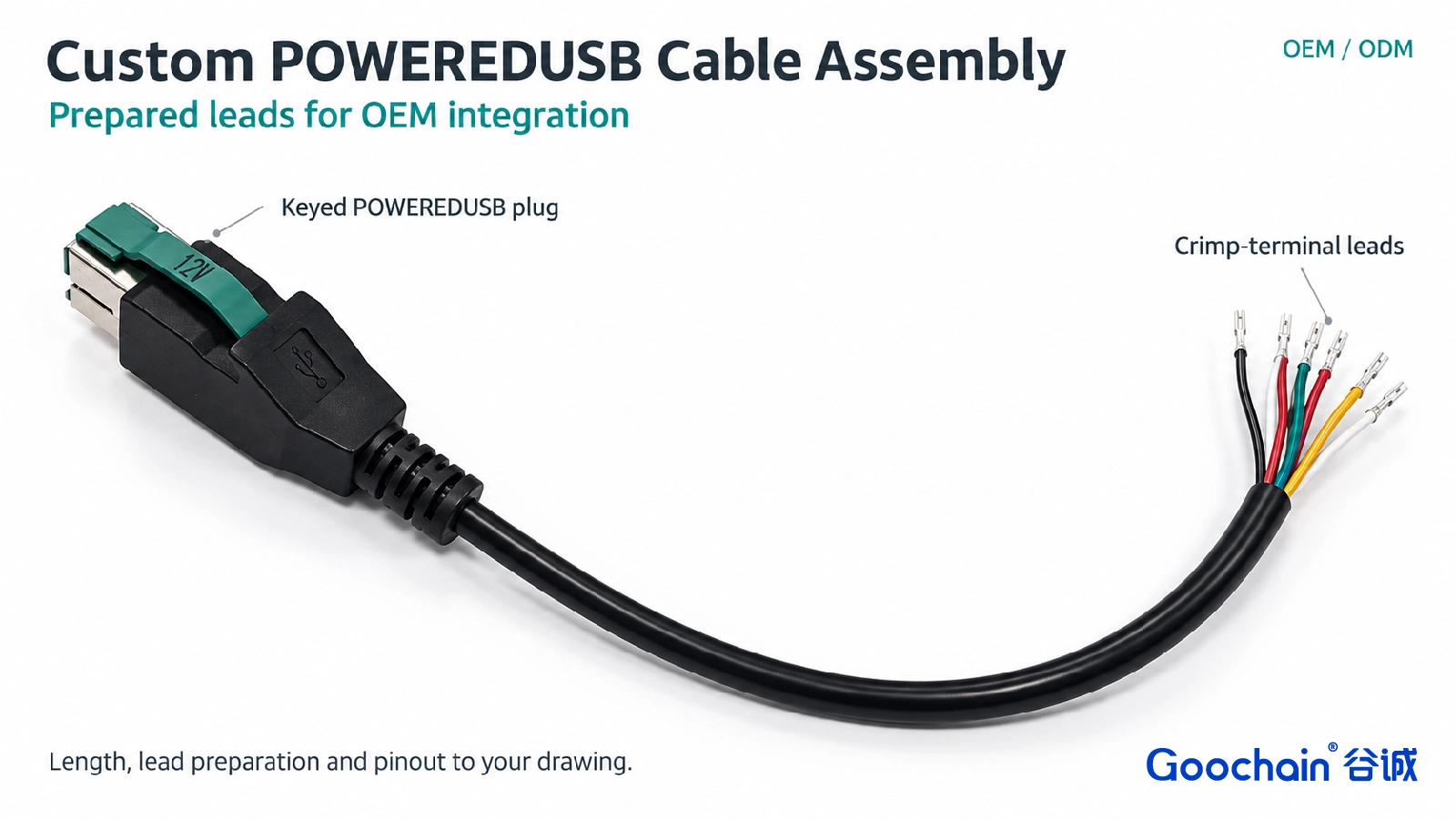
A custom PoweredUSB cable assembly for OEM integration, available with prepared open leads or an equipment-specific internal connector and harness layout. Voltage keying, pinout and terminations follow the approved drawing.
Goochain manufactures OEM PoweredUSB cable assemblies with a defined interface and device-side termination. Choose prepared open leads for a later soldering or crimp process, or specify an internal connector and branch layout for direct equipment integration. Each configuration is reviewed against the host voltage key, pin map, power and data needs, and enclosure space.
A PoweredUSB cable for an OEM device begins with the host port and the equipment wiring drawing. Goochain builds this assembly with a specified voltage-keyed PoweredUSB interface and a device-side termination chosen for the actual production process. The open-lead and internal-harness versions shown below are alternative configurations, not a single fixed pinout.
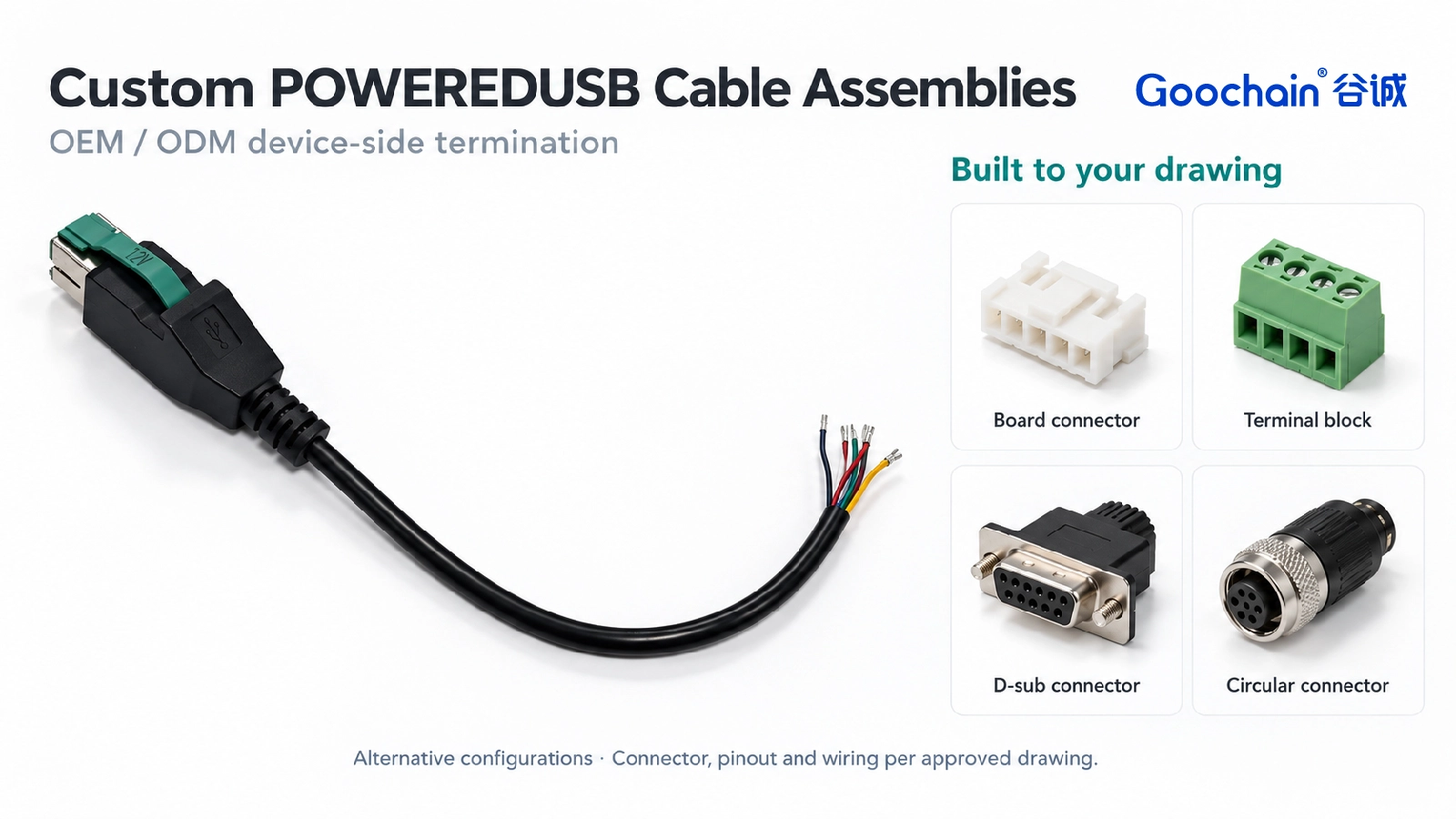
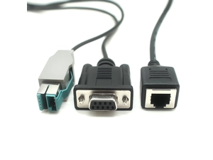
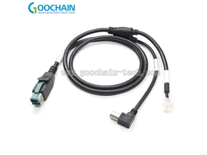
Prepared open leads. The conductors can be stripped, tinned, identified or prepared for the specified terminals. Your team then completes soldering, crimping or connection to its own assembly according to the approved process.
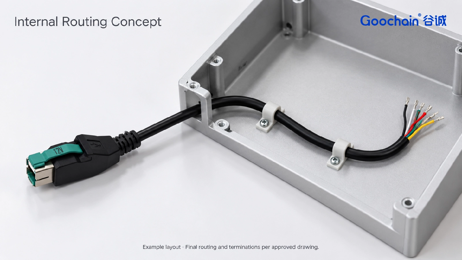
Internal equipment harness. The device end can instead use an approved board connector, terminal or branch arrangement. The mating interface, wire map and cable exit follow the enclosure and assembly drawing.
Specify each breakout length from a common reference point, together with strip length, tinning or terminal requirements and wire identification. This prevents the device-side leads from arriving too short for the intended soldering or crimping step. Labels and protective sleeves can be matched to the installation sequence.
For a finished internal harness, provide the mating connector, branch dimensions, connector orientation and fixing points. Review the sample inside the target enclosure for clearance, cable retention and service access. If your device uses a 1×8 or 2×4 connector, the layouts and mating details need separate checks; our 1×8 vs 2×4 PoweredUSB connector guide explains the distinction.
Choose the PoweredUSB connector gender and 5V, 12V or 24V keying to match the host port. Define whether the assembly carries power only or power plus USB data, then specify conductors, data-pair treatment, shielding and strain relief for that circuit. Wire color by itself does not establish voltage or pin assignment. For a broader interface overview, see our PoweredUSB cable guide to 5V, 12V and 24V connections.
For a quotation, share the host-port voltage and mating connector, pin-to-wire map, device-side termination, breakout or branch dimensions, enclosure layout and expected quantity. A reference sample is helpful when you also identify the required changes. Goochain can review the drawing, make samples and define the inspection points before production. You can also browse the wider PoweredUSB POS equipment cable range for finished device-side connector examples.
Keep required fields minimal. Attach drawings/photos for accurate quoting.
Tip: A simple installation photo often saves 2–3 rounds of questions.
Quotation 1–2 days; development 15–20 days; mass production 20–25 days (project dependent).
Yes. Reference sample + requirements helps confirm drawings and test plan.
Depends on materials and complexity. We support prototypes and scalable mass production.


 English
 简体中文
 Deutsche
 Italian
 français
 Español
 Nederlands
 日本語
 한국어
 عربى
 português
 Türk