

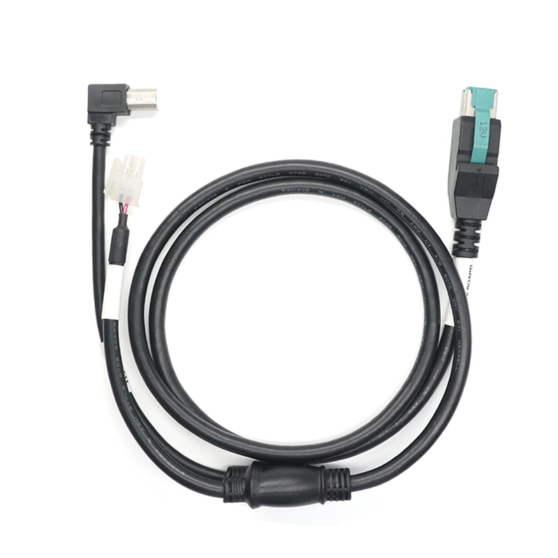
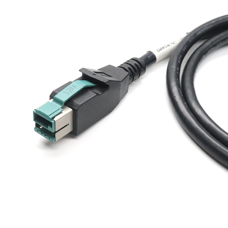
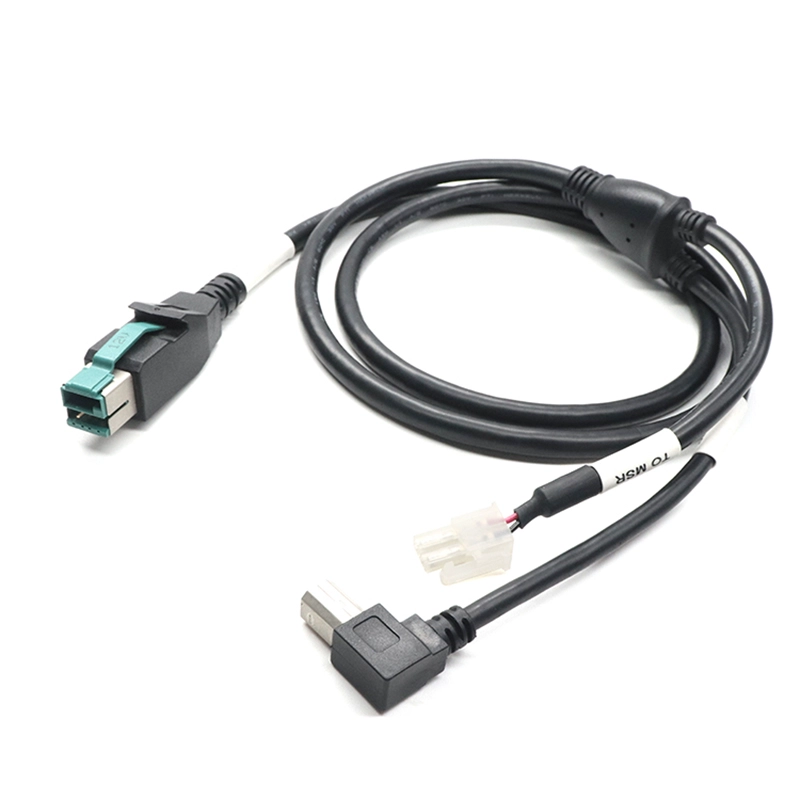
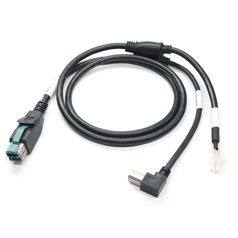
USB-B data and a matched 2-pin power connection for POS peripherals, with defined terminal polarity and connector orientation.
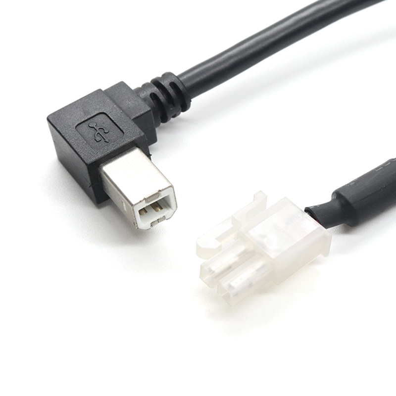
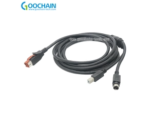
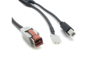
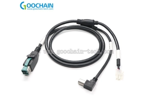
Goochain builds this 12V POWEREDUSB Y cable for a peripheral with a USB-B data socket and a separate 2-pin power connector. The right-angle USB-B plug follows the available installation space, while the power branch uses a housing and contacts selected for the mating connector. Terminal series, pitch, retention and pin polarity are recorded with the branch drawing. The passive assembly routes the host auxiliary supply to the power branch and does not convert voltage. For a device with a DC barrel jack, the POWEREDUSB to USB-B DC Y Cable uses a different power connector.
Goochain manufactures POWEREDUSB cable assemblies with a USB Type-B male data branch and a separate two-position power connector. The configuration suits POS peripherals and OEM equipment that use independent USB-B and two-contact power interfaces.
The power branch is built around the selected connector system: its housing, contacts, mating part and wire assignment. As part of our POWEREDUSB cable range, this assembly can be developed around an existing equipment interface or an approved OEM drawing.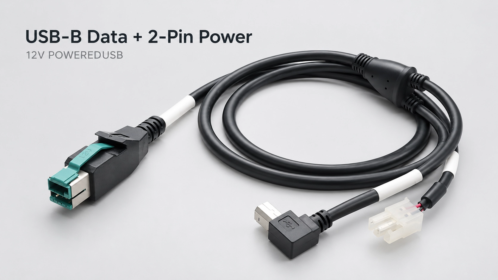
Two power connectors can have the same number of positions while using different contact spacing, keying or retention features. A similar housing shape does not establish compatibility. The connector reference should identify the complete mating system before samples are made.
| Selection point | Details to define |
|---|---|
| Housing and mate | Connector series, housing part number and matching equipment connector or harness. |
| Pitch and keying | Contact spacing, cavity arrangement and the permitted mating orientation. |
| Contacts and wire | Contact type, termination method and compatible conductor and insulation sizes. |
| Retention | The specified latch or friction-fit structure, with enough access for connection and removal. |
A customer-nominated connector can be reviewed from its part number, drawing or mating sample. Any proposed alternative should be checked for fit, contact compatibility and electrical requirements before approval.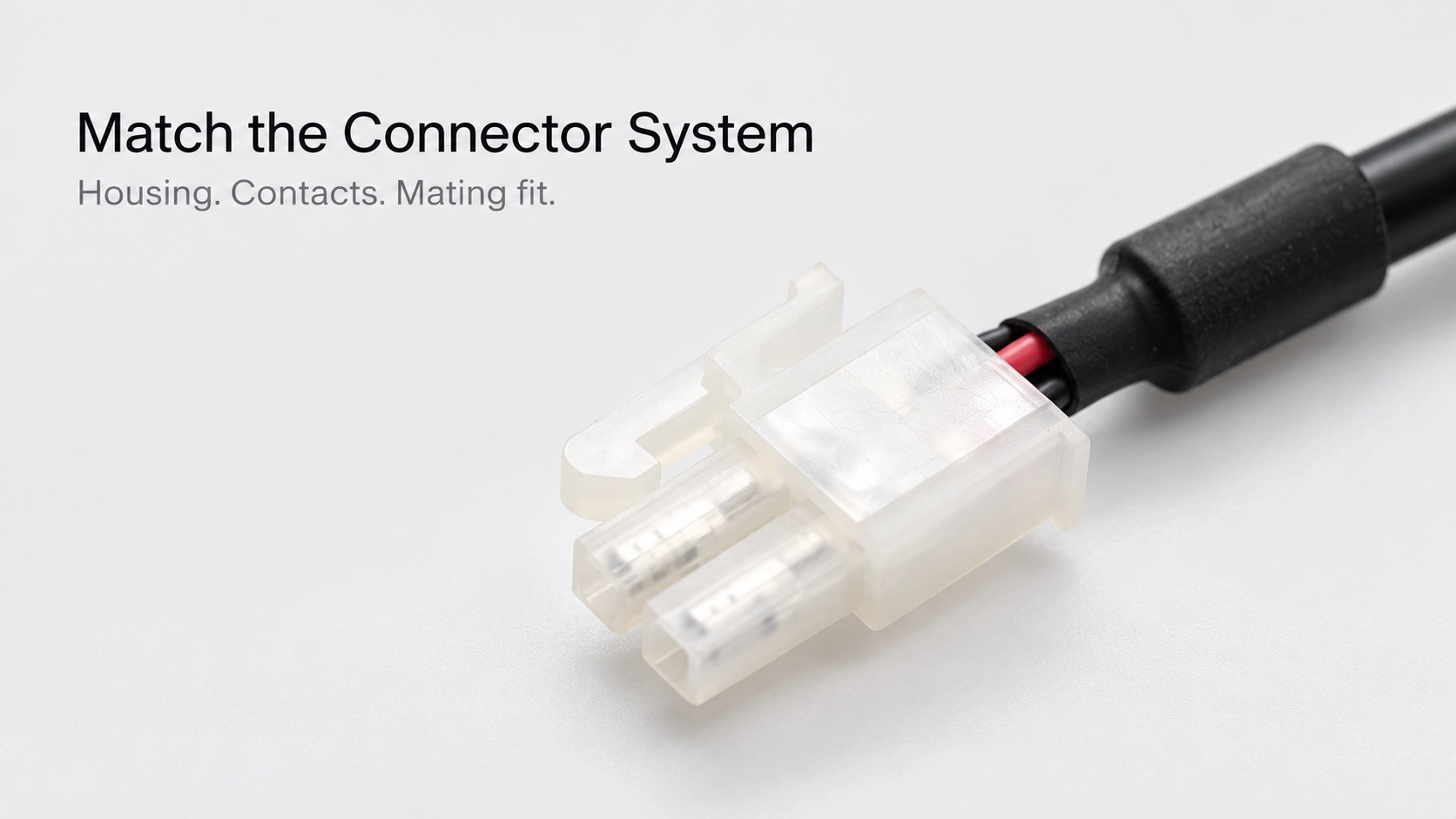
A connector viewed from the mating face appears reversed when viewed from the wire-entry side. The wiring drawing should state the viewing direction, identify the contact positions and assign the supply and return to the correct cavities.
Wire colors and branch labels help identify the assembly during production and service. Electrical checks should still follow the approved pin map, rather than relying on color alone. This is particularly useful when replacement cables must match an existing harness.
Separate USB communication from the auxiliary power path. In the passive configuration, the specified POWEREDUSB auxiliary supply is routed to the two-pin power branch. The USB-B branch follows the approved USB interface wiring. The cable does not automatically regulate or convert the supply voltage.
The USB-B and power branches should reach their mating interfaces with enough free cable for assembly and servicing. Main cable length, split position and each branch length can be defined separately. The installed route should avoid pulling sideways on the connector housing or transferring cable tension directly to the terminals.
Where a locking connector is selected, leave room to operate its release. A straight or angled USB-B exit can be reviewed against the equipment layout; for an angled version, record the exit direction relative to the mating face so the sample follows the intended route.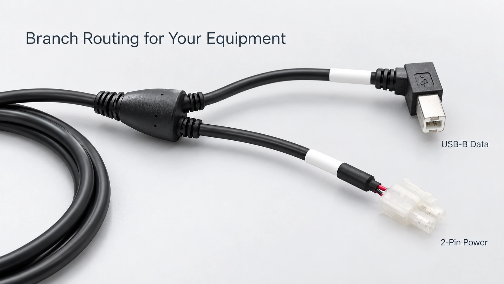
The housing, contact and wire are selected together. For crimped versions, the terminal must suit the conductor and insulation, and the completed contact must seat correctly in the housing. Current capability is assessed for the specified cable assembly and operating conditions, rather than inferred from the two-pin format.
Goochain supports OEM production and ODM development of powered USB harnesses at its 5,000 m² Dongguan facility. Our Factory & Quality process supports inspection against the accepted drawing and sample. Agreed checks can include terminal seating, termination workmanship, continuity, polarity, branch dimensions, required USB function and pull testing where specified.
To start a sample review, provide the host voltage and keying, two-pin housing and mating-part references, contact assignment, required current, USB-B exit direction and branch lengths. Include a reference cable or equipment-interface photo and your target quantity.
Keep required fields minimal. Attach drawings/photos for accurate quoting.
Tip: A simple installation photo often saves 2–3 rounds of questions.
Quotation 1–2 days; development 15–20 days; mass production 20–25 days (project dependent).
Yes. Reference sample + requirements helps confirm drawings and test plan.
Depends on materials and complexity. We support prototypes and scalable mass production.


 English
 简体中文
简体中文  Deutsche
  Italian
  français
  Español
  Nederlands
  日本語
日本語  한국어
한국어  عربى
عربى  português
  Türk
Türk 

