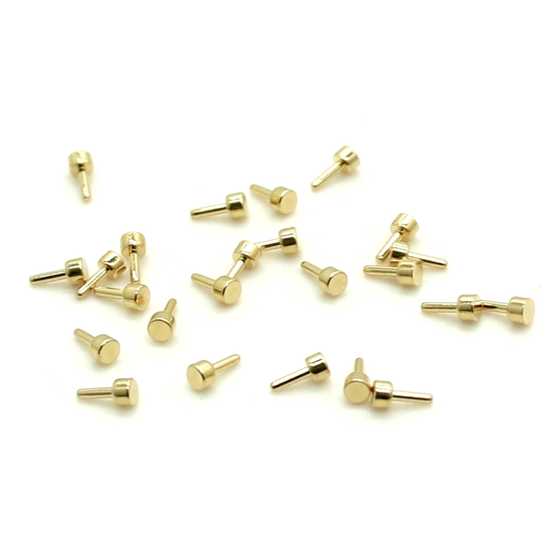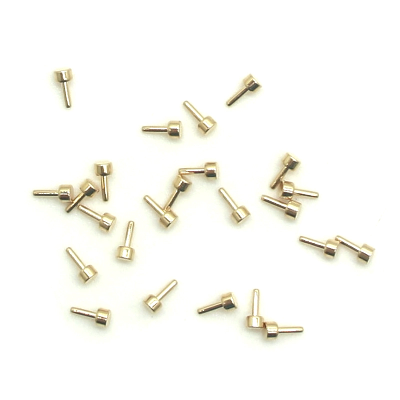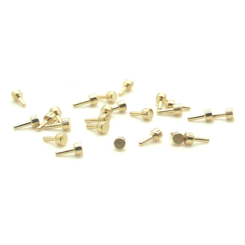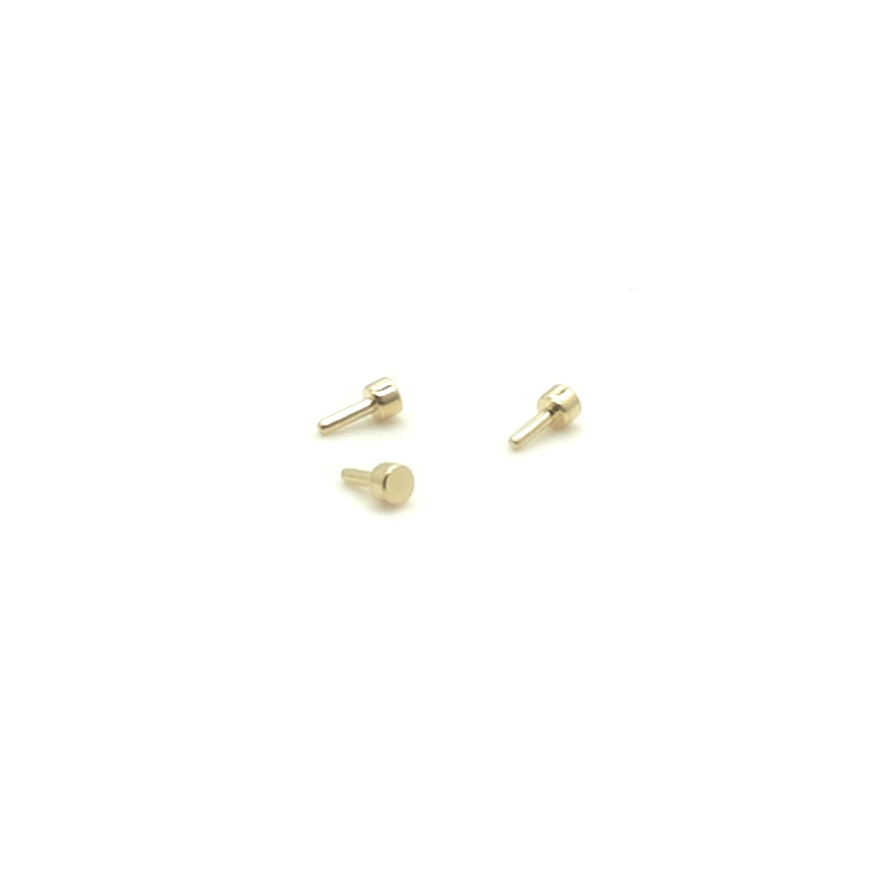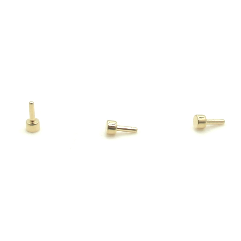


A gold-plated solid contact component with a nominal 1.5 mm diameter and 3.3 mm overall length.
This compact solid contact pin has a nominal 1.5 mm diameter and 3.3 mm overall length with a gold-plated surface. Use the approved part drawing to define base material, end shape, fit, plated area and finish acceptance for the connector assembly.
This compact solid contact pin has a nominal 1.5 mm diameter and 3.3 mm overall length with a gold-plated surface. Use the approved part drawing to define base material, end shape, fit, plated area and finish acceptance for the connector assembly.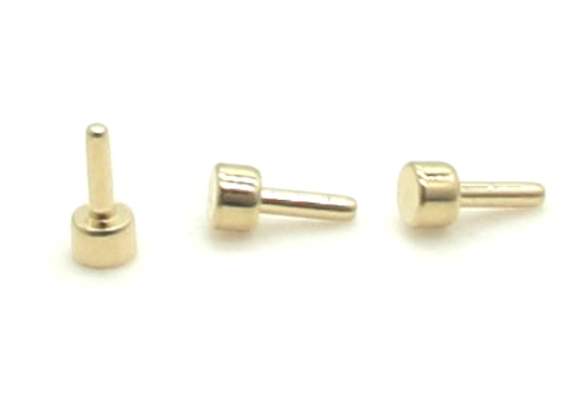
Use the part drawing to define the diameter and overall length datums, end profile and required fit. Where the mating side needs spring movement, use the gold-plated PCB test probe as a reference for the spring-contact side. Confirm the proposed footprint and contact position against the fixed pin and the board layout.
Call out the plated areas and base material separately. If a thickness is required, give its unit, minimum or nominal basis, and the agreed method for confirming it.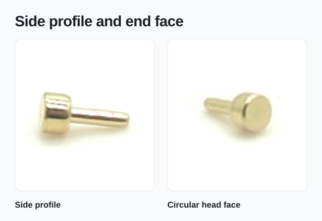
Use the connector assembly drawing to establish contact location, engagement and assembly tolerances. When the pin forms part of a cable or docking assembly, the custom Pogo Pin cable RFQ guide helps define the mechanical information, electrical requirements and sample checks to include in the order.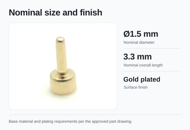
Send the part drawing, mating details, base material, gold finish callout, inspection requirements and quantity.
Keep required fields minimal. Attach drawings/photos for accurate quoting.
Tip: A simple installation photo often saves 2–3 rounds of questions.
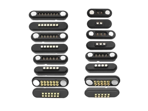
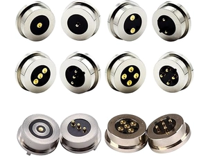
Quotation 1–2 days; development 15–20 days; mass production 20–25 days (project dependent).
Yes. Reference sample + requirements helps confirm drawings and test plan.
Depends on materials and complexity. We support prototypes and scalable mass production.


 English
 简体中文
 Deutsche
 Italian
 français
 Español
 Nederlands
 日本語
 한국어
 عربى
 português
 Türk