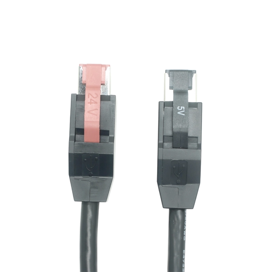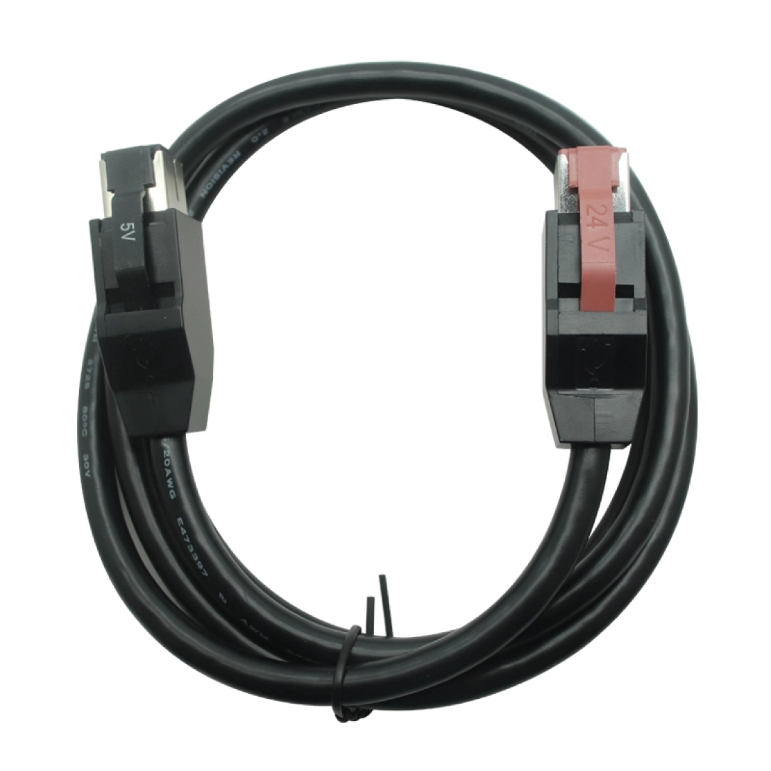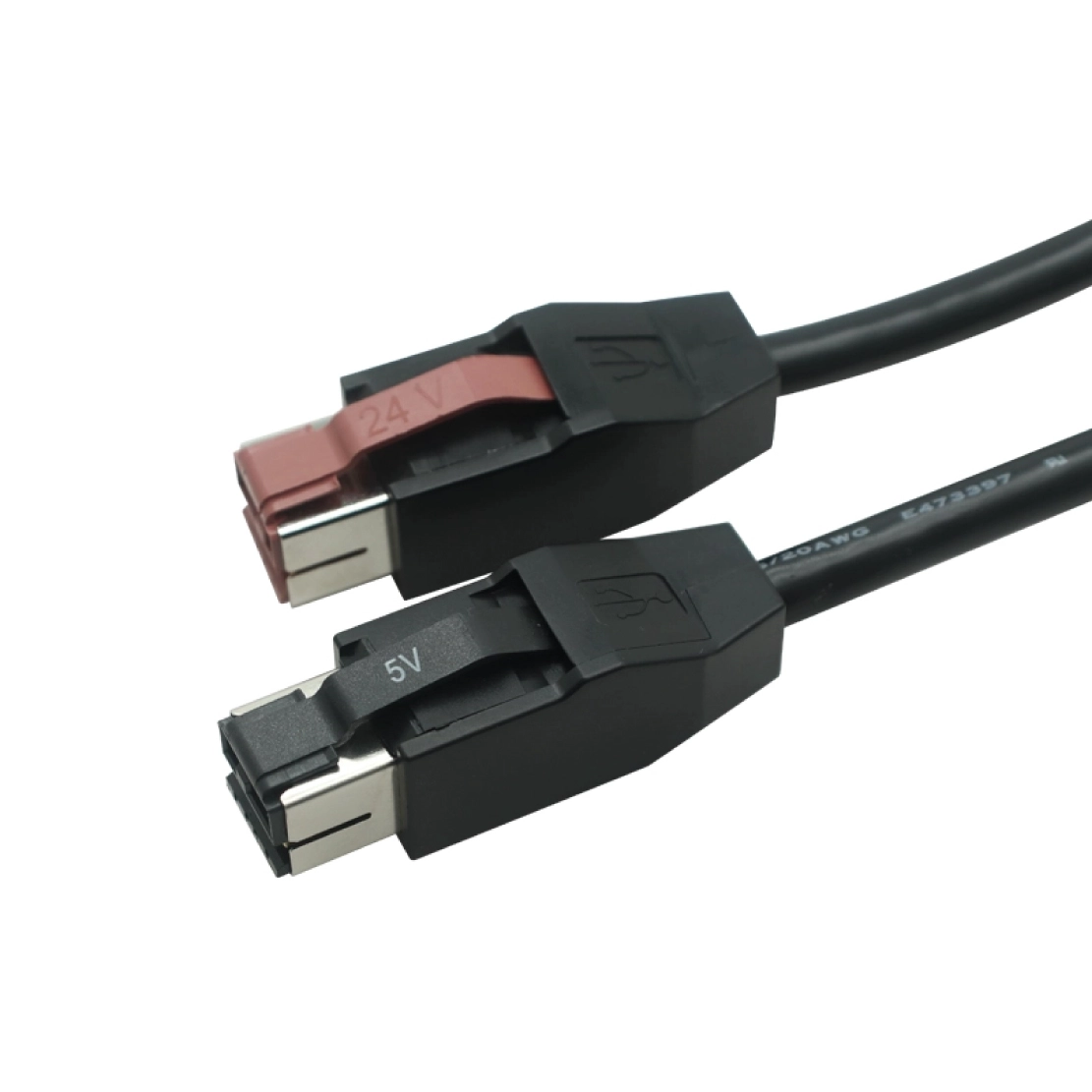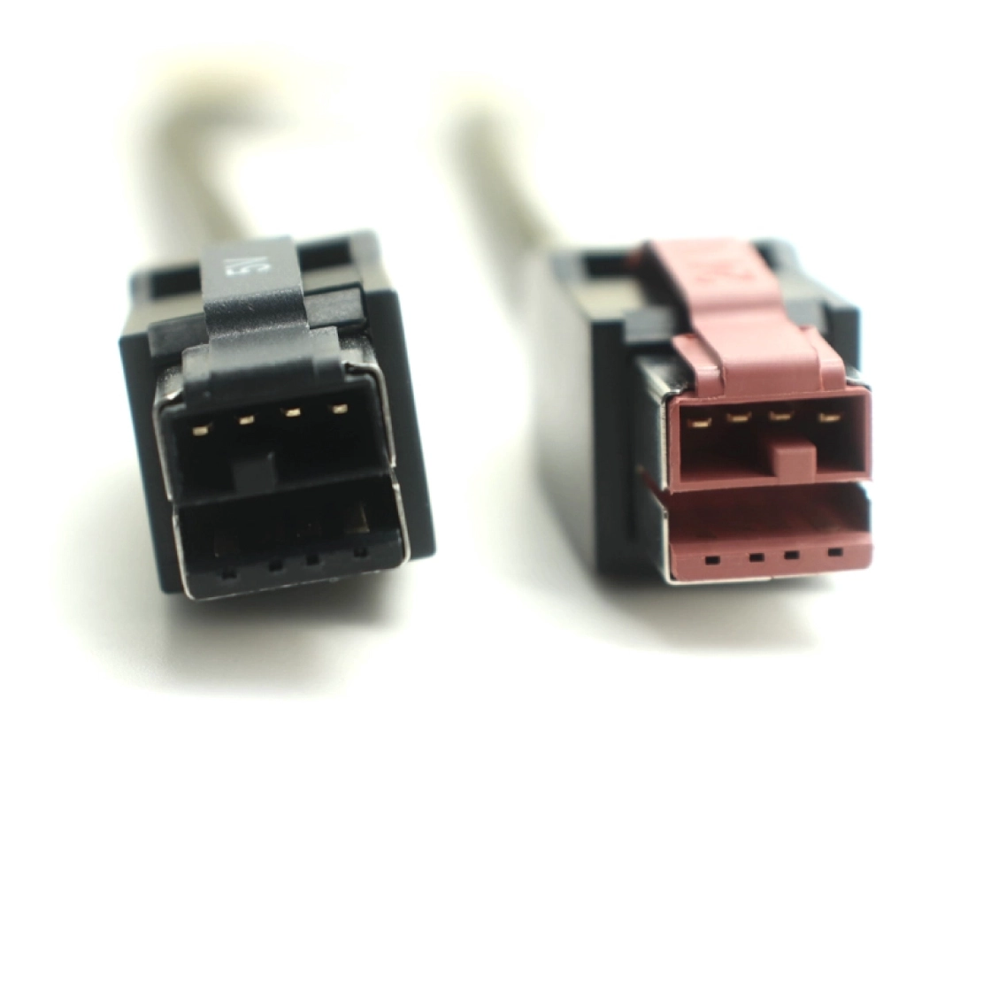


Device-specific 5V PoweredUSB cable built around the peripheral connector, pinout, power load and required USB function.
Goochain develops 5V PoweredUSB cable assemblies for POS peripherals that cannot be defined by the host plug alone. The device-side connector, pin assignment, power requirement and USB function are reviewed together so the finished cable matches the actual hardware rather than a generic connector description. Power-only and data-enabled versions are treated as different electrical configurations. For OEM and ODM projects, Goochain can develop the cable length, conductor construction, connector overmold, exit direction and strain relief around the equipment layout, then support sample evaluation and controlled production at its 5,000 m² Dongguan factory.
Goochain manufactures custom 5V POWEREDUSB cable assemblies for OEM POS equipment. Each assembly pairs a 5V-keyed host interface with the connector and wiring required by the peripheral. Power-only and USB data-with-power versions are available as separate designs, with cable length, conductor size and molded exits selected for the installation.
For a reader, scanner accessory or other peripheral using the matching 5V interface, the starting point is the equipment connection: its mating connector, pin assignment and operating load. These details define the cable that purchasing teams order and installers fit.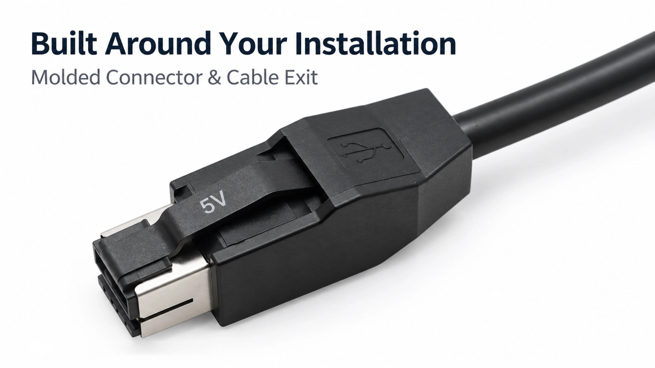
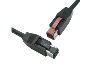
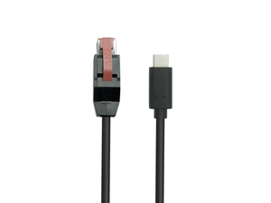
The host plug identifies only one end of the assembly. At the peripheral, the connector housing, contact arrangement, latch and pinout must all match. A front-view connector photo helps identify the mechanical interface; a pin assignment confirms where the supply, return and any USB conductors must connect.
For replacement projects, a reference cable and equipment model help establish the starting configuration. For a new design, the mating connector drawing and available space around the port allow the device end to be developed with the enclosure. Other voltage and device-end formats are available within our PoweredUSB Cable range.
The following items are selected for each custom assembly. Final specifications are recorded on the approved cable drawing.
| Item | Custom Configuration |
|---|---|
| Host interface | 5V-keyed POWEREDUSB interface |
| Device interface | Connector, terminal or open end matched to the equipment drawing |
| Electrical function | Power only, or USB data with power, according to the selected design |
| Pin assignment | Documented host-to-device wiring map |
| Length and conductors | Selected for the installed route, operating load and allowable voltage drop |
| Connector construction | Overmold, cable exit and strain relief matched to the installation |
| USB requirements | Signal path, shielding and target operating speed defined for data-enabled versions |
| Supply model | OEM drawing-based production or ODM development |
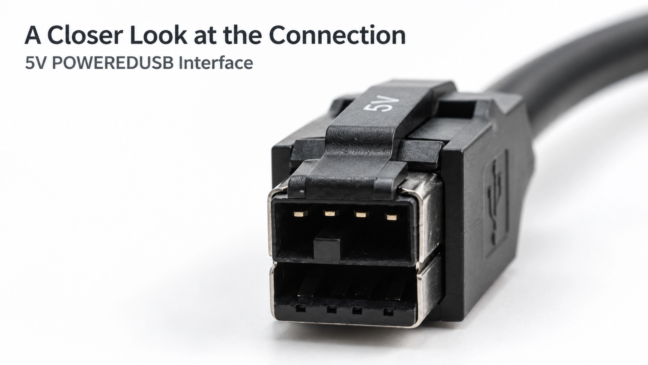
A power-only build needs a defined supply and return path. A data-enabled build also requires the USB conductors, connector contacts and shielding arrangement needed for the intended connection. The finished assembly should be evaluated with the selected host and peripheral.
Cable length and device load are reviewed together when choosing the conductors. The current requirement belongs to the complete assembly, rather than being inferred from the host plug alone. Where power-only and data-enabled versions look similar, separate part numbers and clear labeling help service teams select the correct replacement.
Behind a POS display or inside a counter, the connector body and strain relief need room as well as the cable itself. The exit direction should allow the plug to seat fully, leave access to the latch and keep the cable clear of enclosure edges. Installation photos help identify restrictions that a cable-length measurement can miss.
Goochain can review the connector overmold, strain-relief profile and cable route together. Samples provide a practical way to check fit before the same geometry is released for production.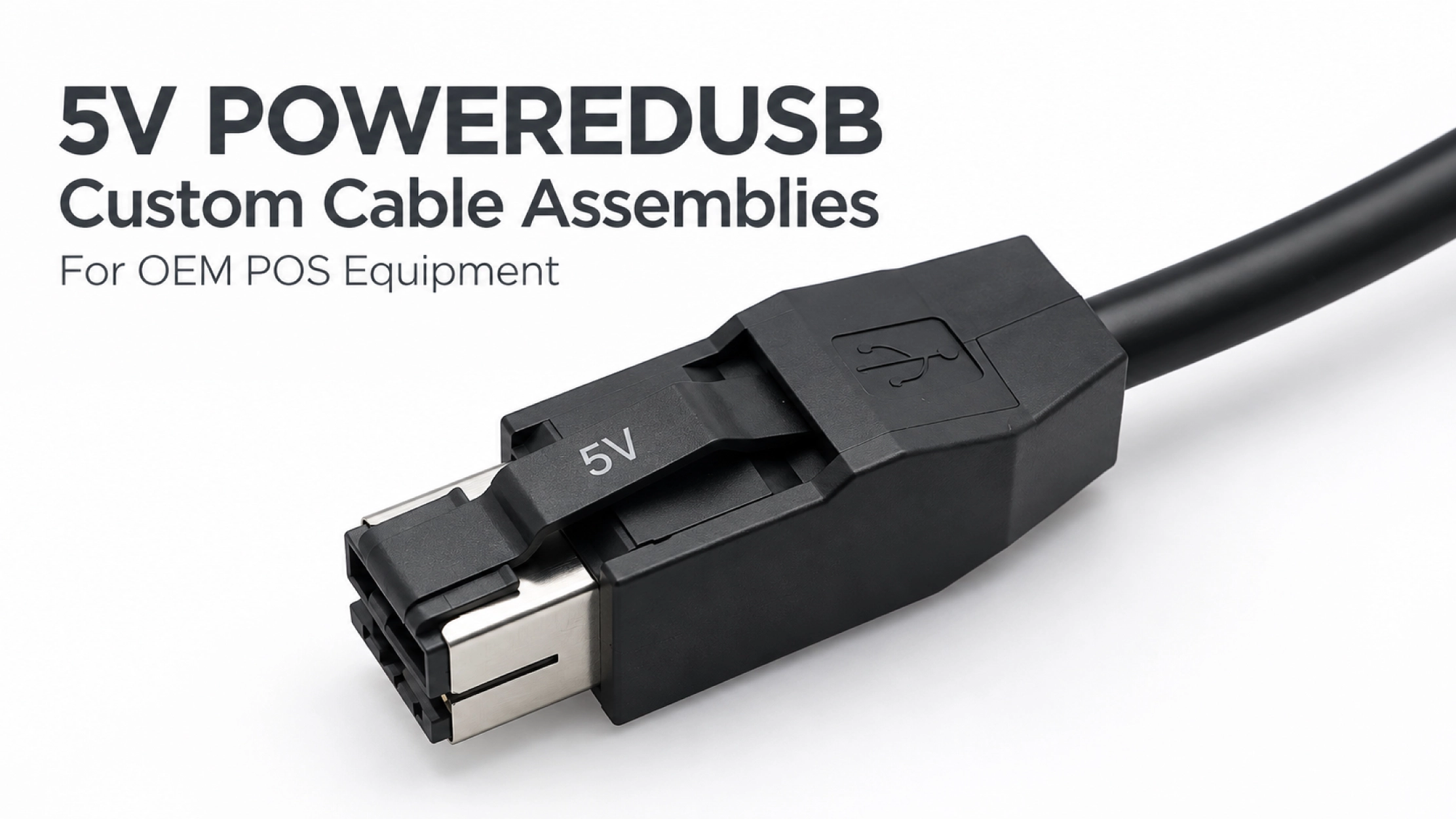
Goochain develops and manufactures powered USB assemblies at its 5,000 m² facility in Dongguan, China. OEM work follows the approved connector selection and wiring drawing. For ODM projects, our engineering support covers interface review, component selection, molded structures and sample development around the equipment layout.
Sample approval can include connector-fit checks, wiring verification and the required power and USB functions. The approved configuration then provides the reference for production inspection. Our Factory & Quality page outlines incoming, in-process and final inspection across our manufacturing operations.
No. The device connector and pinout must match as well as the voltage. Similar-looking housings can use different wiring, so the equipment interface should be confirmed before ordering.
Yes, as a revised design. The conductor arrangement, connector contacts and USB requirements need to be reviewed, followed by evaluation of the new assembly with the intended equipment.
Send the 5V host interface, device connector drawing or reference sample, pin assignment, installed length and operating load. Include the required USB function, an installation photo and target quantity so we can define the first sample and quotation.
Keep required fields minimal. Attach drawings/photos for accurate quoting.
Tip: A simple installation photo often saves 2–3 rounds of questions.
Quotation 1–2 days; development 15–20 days; mass production 20–25 days (project dependent).
Yes. Reference sample + requirements helps confirm drawings and test plan.
Depends on materials and complexity. We support prototypes and scalable mass production.


 English
 简体中文
简体中文  Deutsche
  Italian
  français
  Español
  Nederlands
  日本語
日本語  한국어
한국어  عربى
عربى  português
  Türk
Türk