

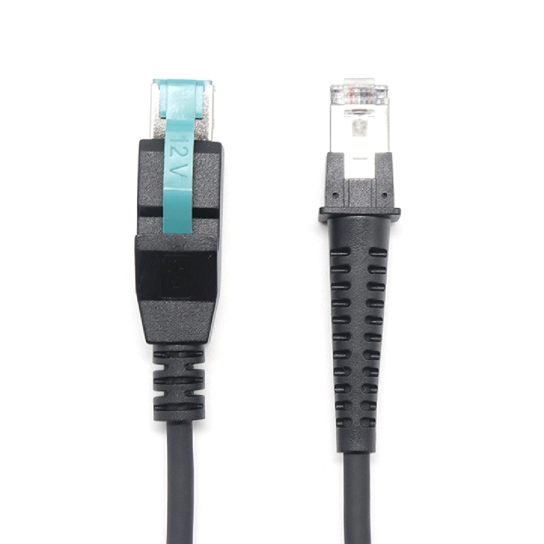
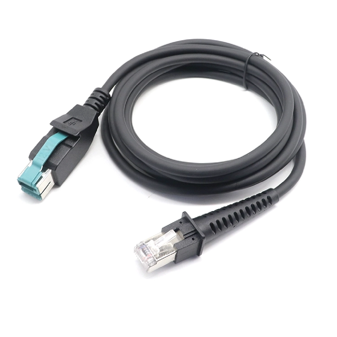
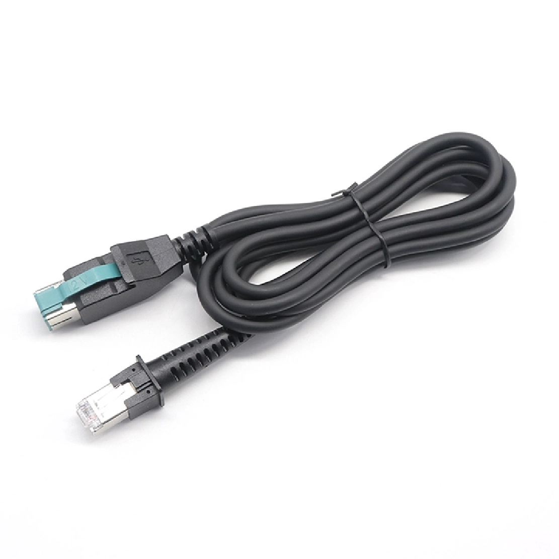
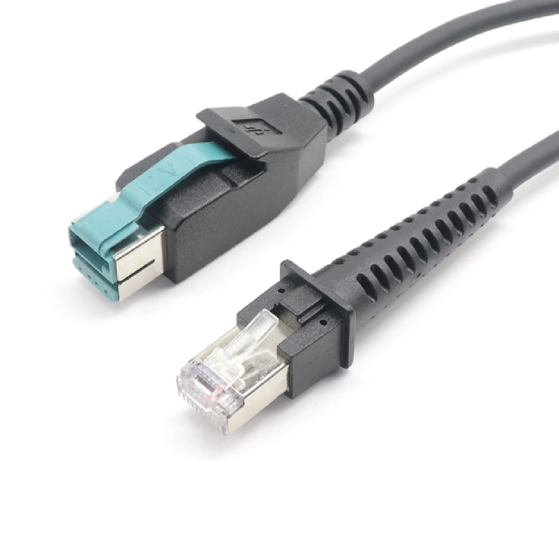
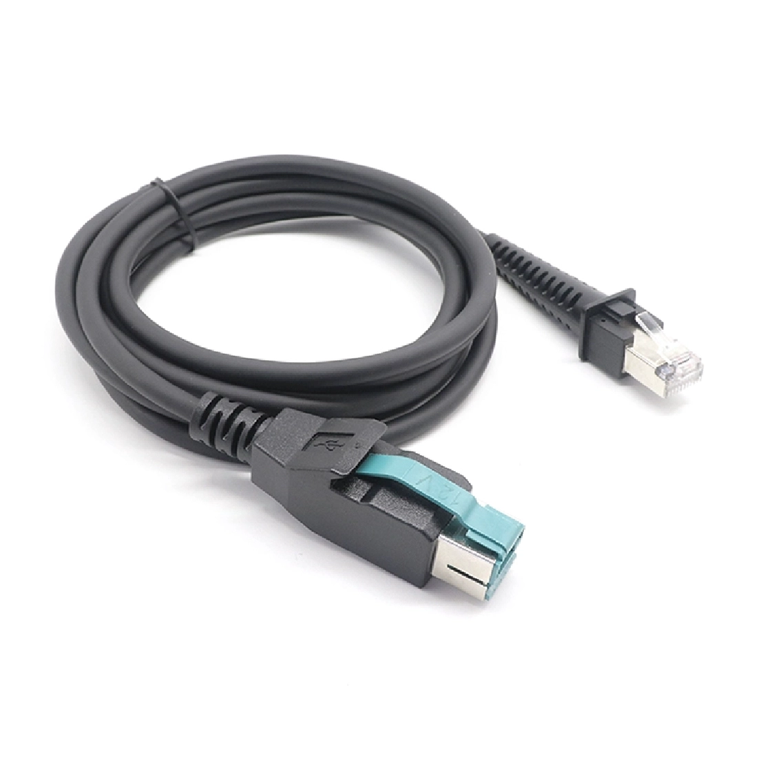
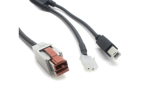
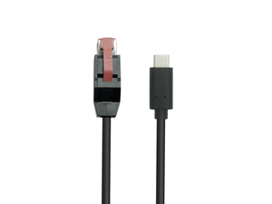
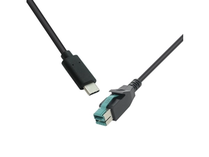
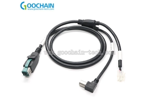
A straight scanner cable with a 12V-keyed POWEREDUSB host plug and an RJ50 10P10C device plug, wired for the specified scanner model.
Goochain builds this straight scanner cable between a 12V-keyed POWEREDUSB host connection and an RJ50 10P10C scanner interface. The ten-contact plug is selected for the actual scanner socket, with power, signal and unused contacts recorded in a model-specific pin map. The cable route includes enough free length for the scan position and connector release. The Datalogic Gryphon reference requires confirmation of the exact model and connection mode; other scanners are reviewed individually against their connector and electrical requirements.
Goochain manufactures straight scanner cable assemblies connecting a 12V POWEREDUSB host port to a specified RJ50 10P10C scanner interface. Power and data connections follow the approved scanner pin map, while the modular-plug housing, cable length and strain relief are selected for the equipment and its working position.
Designed for compatible barcode-scanning installations at checkout counters, service desks and self-service kiosks, this assembly provides a defined cable route between the host and scanner. It forms part of our POWEREDUSB POS Equipment Cable range, with each build specified for the target device rather than treated as a universal scanner cord.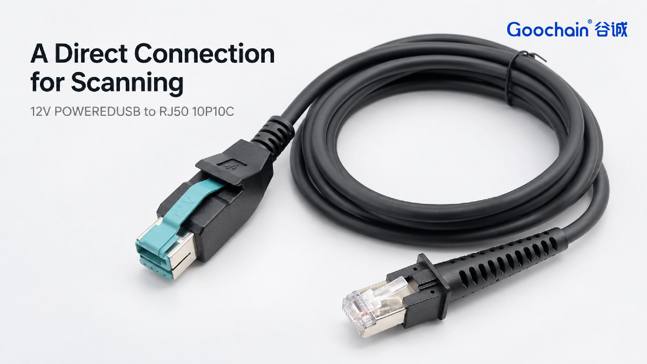
The RJ50 10P10C plug provides ten contact positions, but its appearance does not establish the wiring. Different scanners can assign supply, ground, data and other functions differently. A mechanically fitting plug therefore needs a verified contact map for the exact scanner model and selected connection mode.
The drawing should identify both connector views and the function of each used contact, including positions that must remain unconnected. It should also confirm how the host supply is routed and whether shield termination is required. Connector count alone does not establish the communication protocol or data rate.
| Specification item | Definition for the cable drawing |
|---|---|
| Host connection | 12V-keyed POWEREDUSB interface, host port reference and required wiring. |
| Scanner connection | RJ50 10P10C plug, exact housing, latch geometry and socket access. |
| Electrical mapping | Scanner-specific contact assignment, interface requirements and any unused positions. |
| Cable construction | Straight cable length, conductor selection, jacket, strain relief and shielding where specified. |
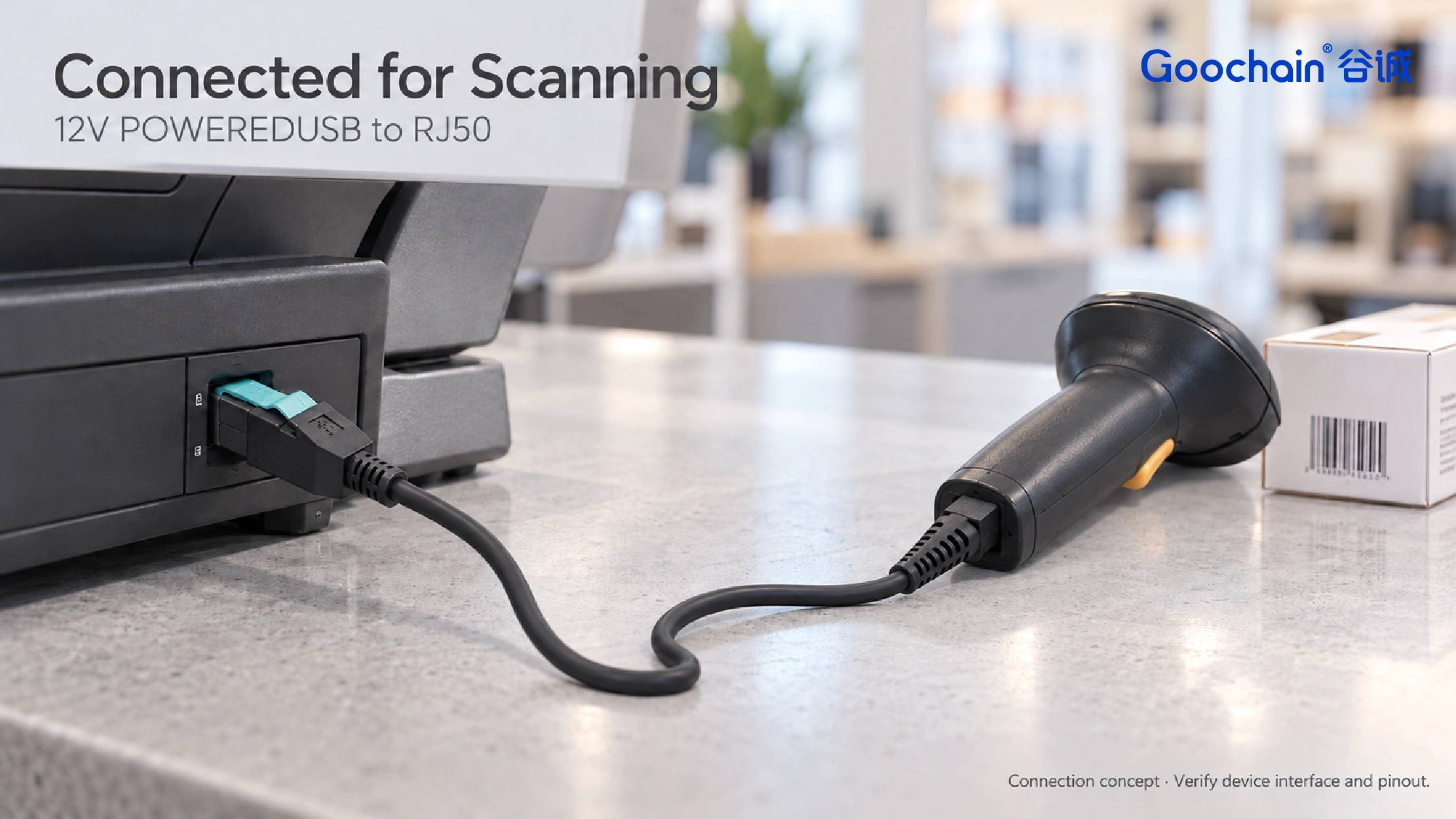
A straight cable suits installations where the route can be planned and spare length can be secured. For a fixed scanner, measure the actual path through the counter or kiosk, including routing openings and the space needed to reach both ports. Leave enough service length to withdraw or reposition the unit without loading the connectors.
For a handheld scanner, include the distance from its resting position to the furthest normal scan point. Keep the moving section free of snag points and avoid fixing the cable immediately behind the scanner plug. The connector, strain relief and relaxed cable bend should all fit the available space, with access to the modular latch for removal.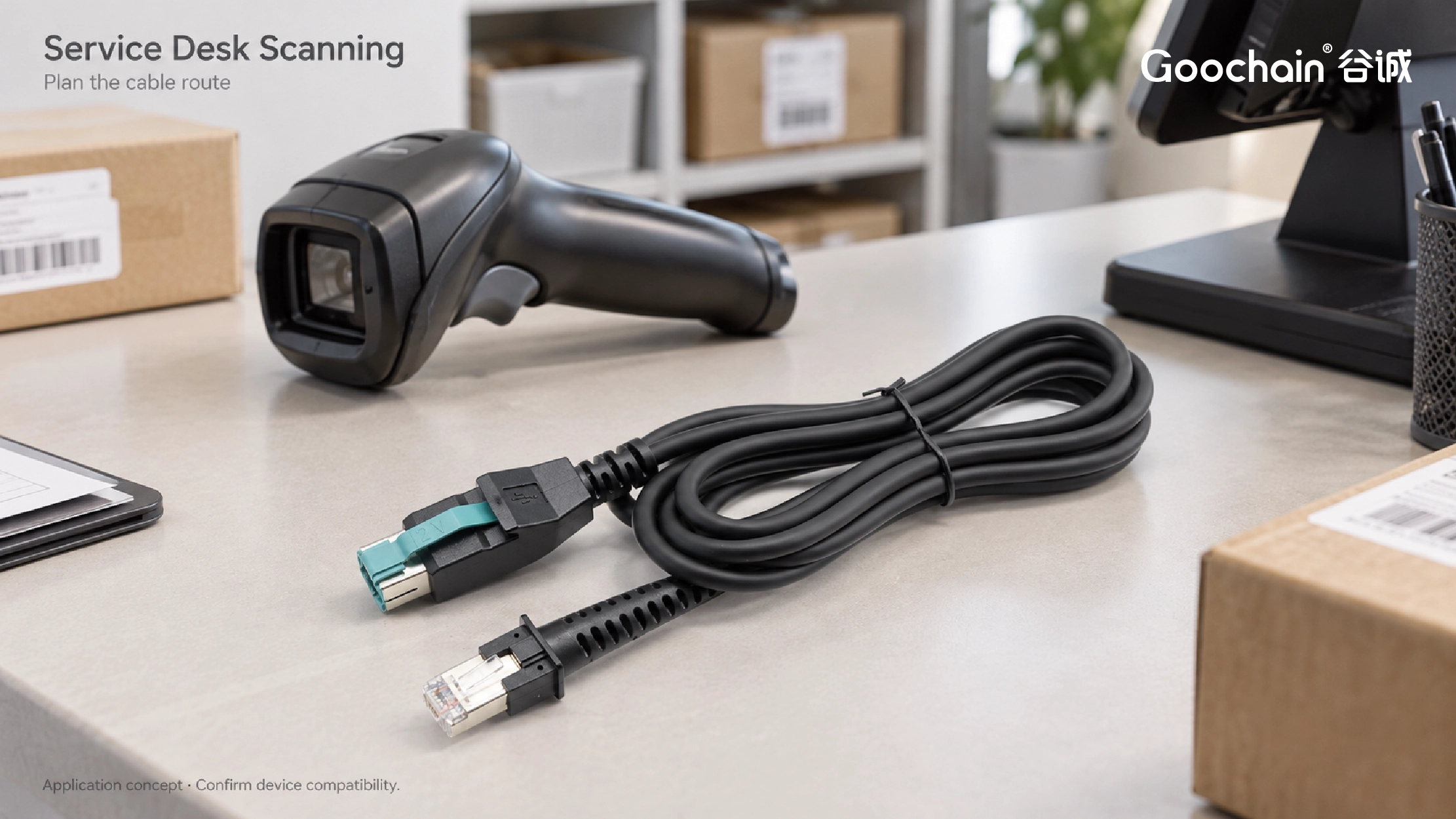
An existing working cable can help establish the plug construction and installed length. Combine it with the scanner documentation to define the replacement drawing, including the contact map, shield connections where applicable and part identification. Sample evaluation should cover both physical fit and operation with the intended host and scanner configuration.
Goochain supports OEM production and ODM development of powered USB cable assemblies in Dongguan, China. Our Factory & Quality process covers incoming material inspection, assembly workmanship and final checks. The project inspection plan can specify wiring continuity, connector dimensions, cable length, labeling and agreed functional checks against the approved sample.
Is RJ50 the same as an RJ45 network connection?
No. RJ50 here identifies a ten-position, ten-contact modular plug. It should not be substituted with an eight-contact Ethernet plug or assigned an Ethernet wiring pattern.
Will this cable work with any scanner that has a ten-contact socket?
Compatibility requires the correct housing, latch, pinout, power requirements and communication interface for the specific scanner. A matching contact count alone is insufficient.
What should be supplied for a replacement or custom length?
Provide the scanner model, host-port details, connection mode and an approved pin map or working reference cable. Include the required route length and scanner movement so the finished length includes usable service allowance.
Request a scanner cable sample. Send your connector photos or drawing, electrical requirements, installed cable route and target quantity. Goochain can review the interface and construction before confirming the sample specification.
Keep required fields minimal. Attach drawings/photos for accurate quoting.
Tip: A simple installation photo often saves 2–3 rounds of questions.
Quotation 1–2 days; development 15–20 days; mass production 20–25 days (project dependent).
Yes. Reference sample + requirements helps confirm drawings and test plan.
Depends on materials and complexity. We support prototypes and scalable mass production.


 English
 简体中文
简体中文  Deutsche
  Italian
  français
  Español
  Nederlands
  日本語
日本語  한국어
한국어  عربى
عربى  português
  Türk
Türk 

