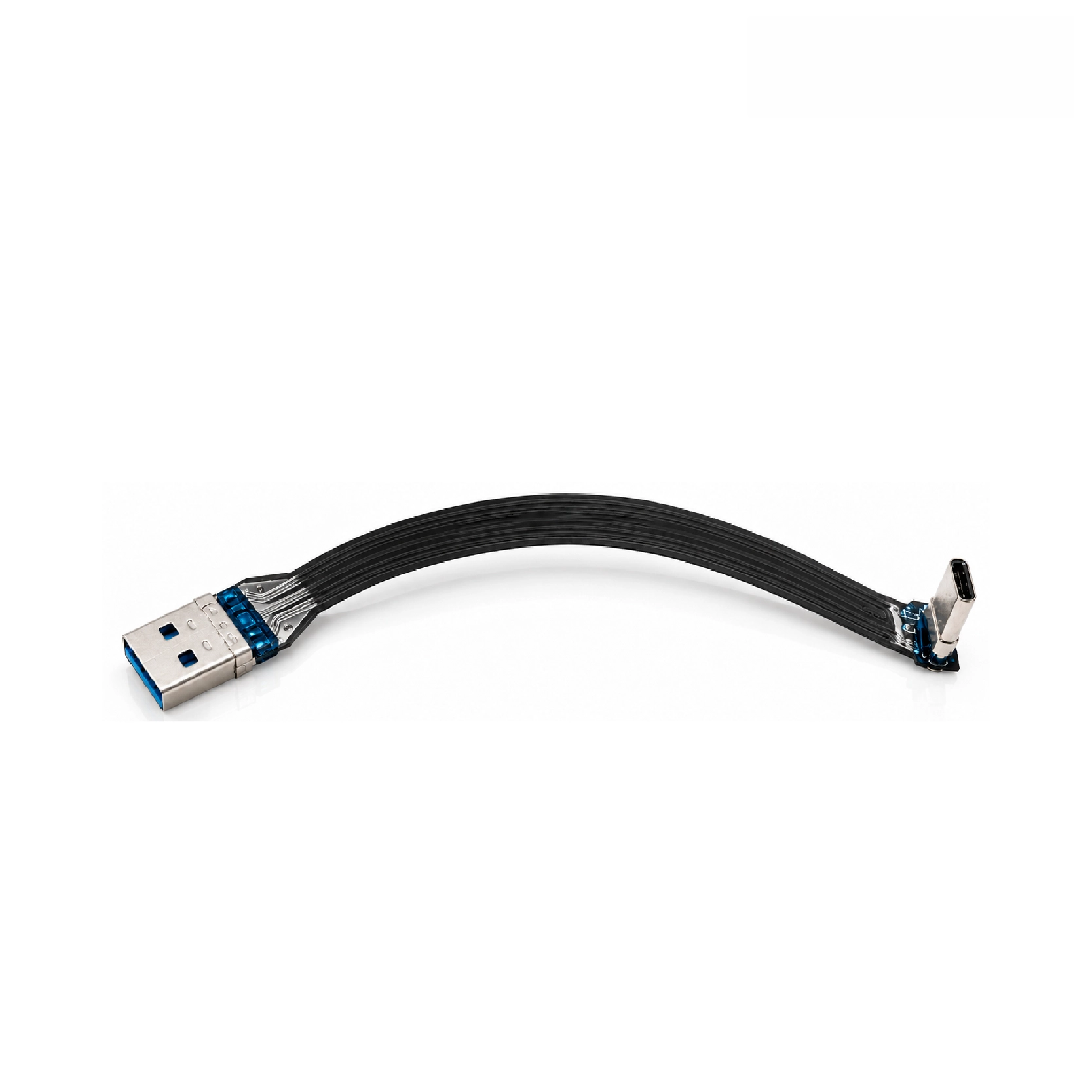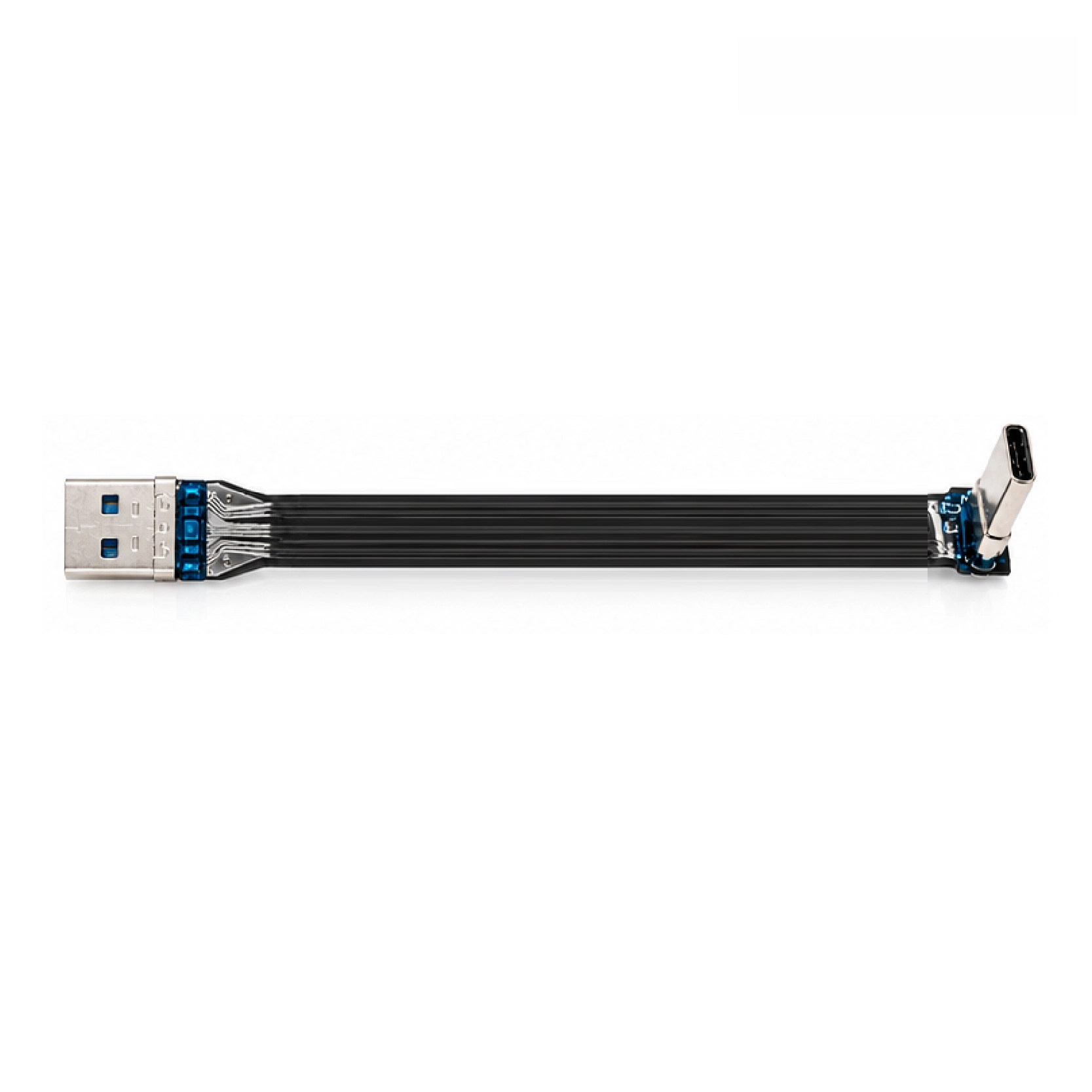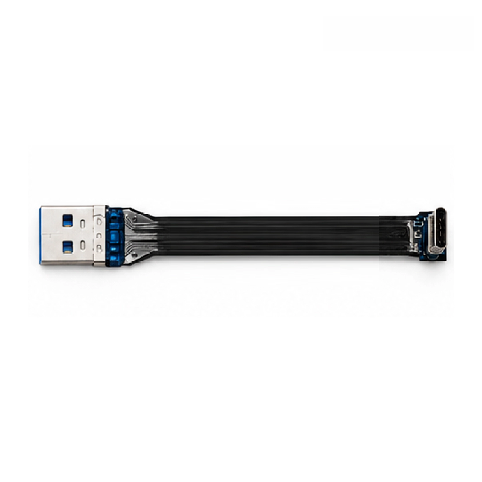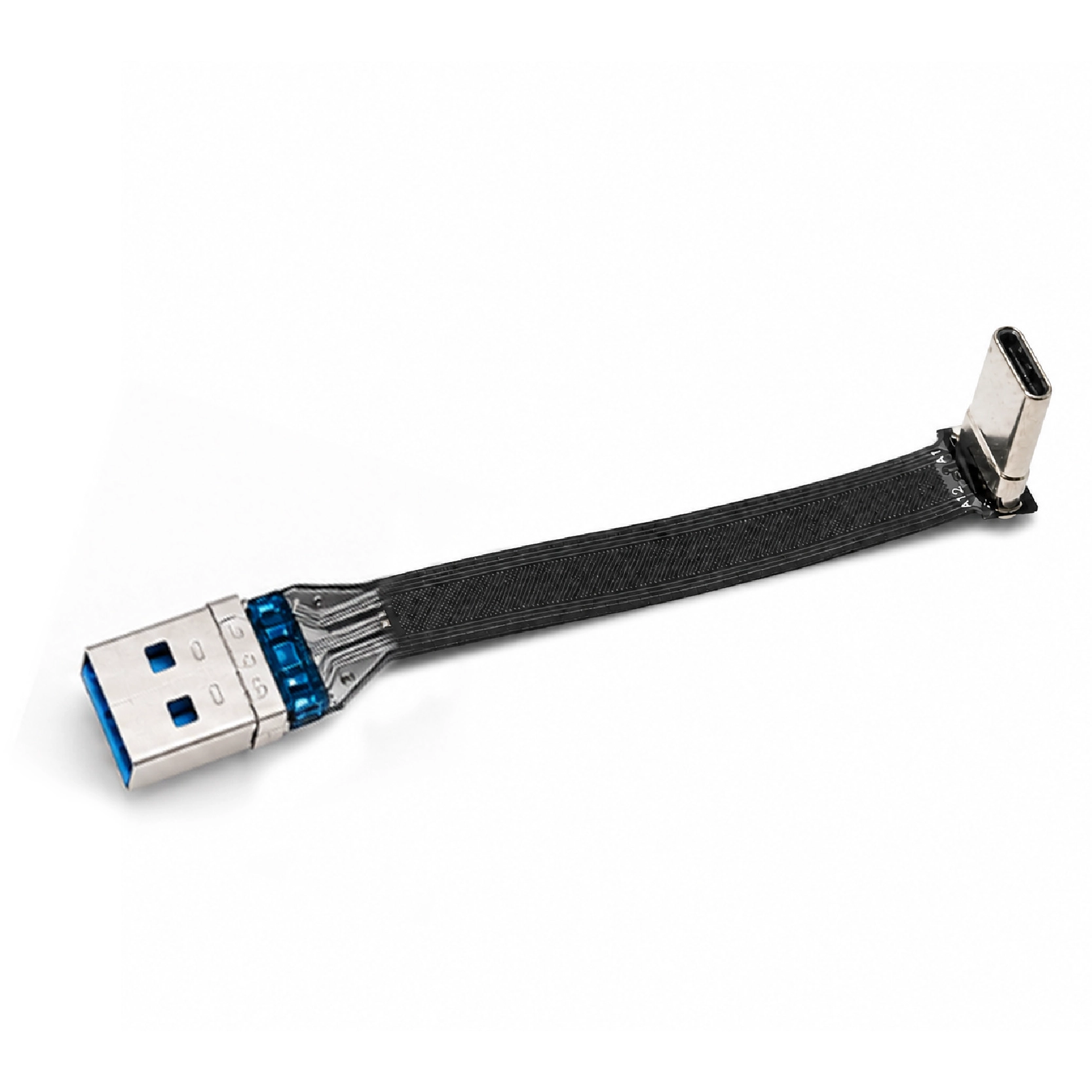


USB 2.0 flat ribbon cable with a 90-degree USB-C plug for compact equipment and limited connector clearance.
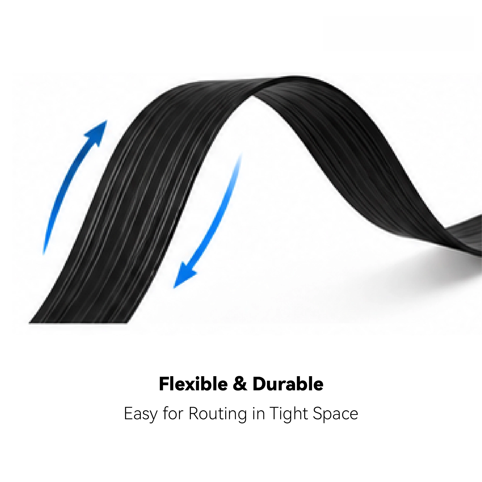
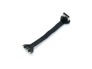
Goochain manufactures this USB 2.0 FPC ribbon cable with a USB-A male plug and a 90-degree USB-C male plug. The angled connector directs the cable along the device housing, helping it fit beside covers, brackets and nearby components. Its flat body suits short internal routes in compact equipment. Cable length, exit direction and connector housing arrangement can be customized to the installation.
Goochain manufactures this USB 2.0 FPC ribbon cable with a USB-A male plug and a 90-degree USB-C male plug. It connects a USB-A source to compatible USB-C equipment while keeping the device-side cable exit close to the enclosure. The flat flexible printed circuit provides a routing option for compact assemblies, equipment brackets and short connections with limited clearance.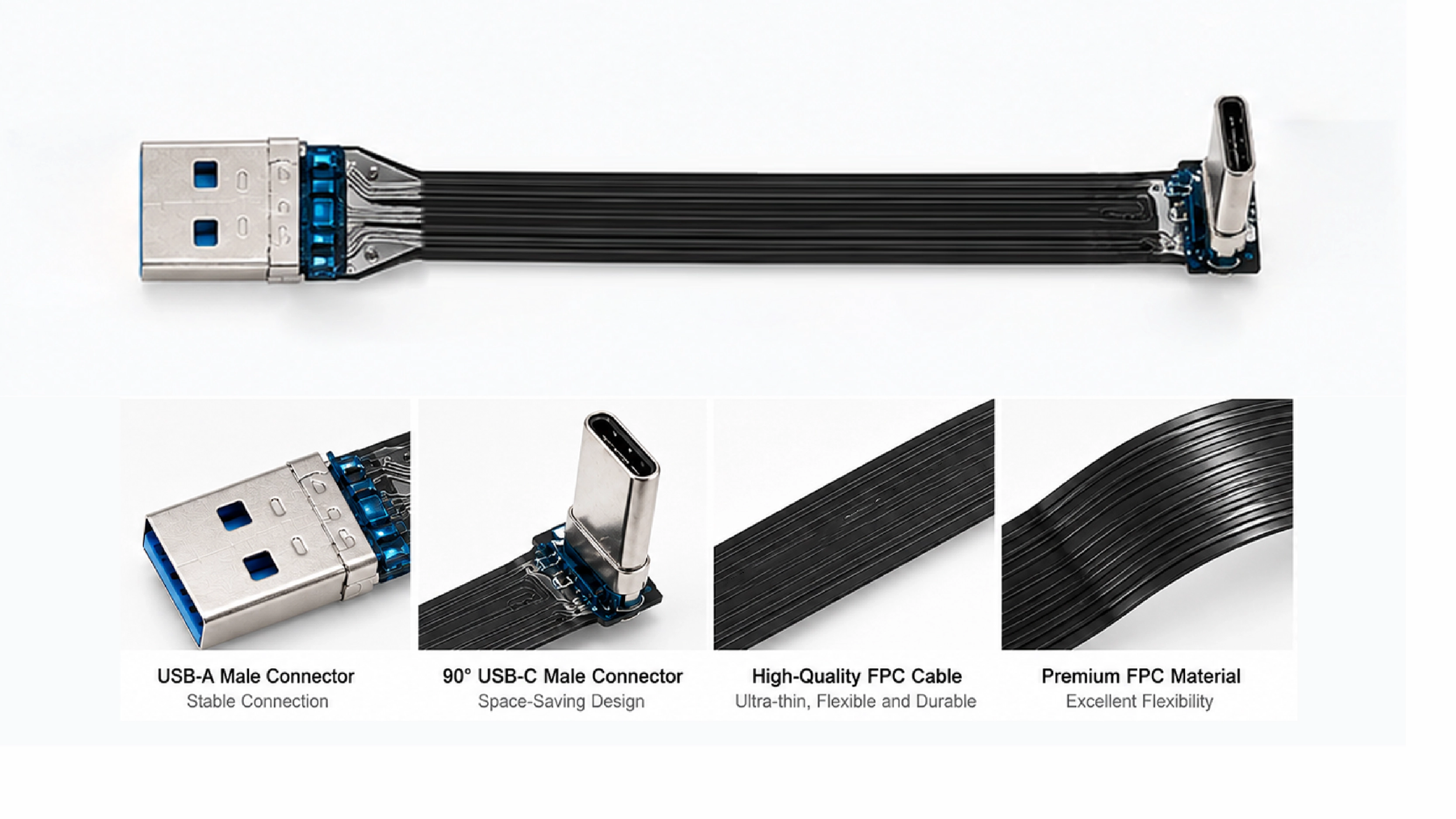
| Item | Specification |
|---|---|
| Brand | Goochain |
| Model | E-24022202 |
| Connection | USB-A male to USB-C male |
| Cable structure | FPC ribbon cable |
| USB-C orientation | 90-degree male plug; cable exit direction to drawing |
| Data version | USB 2.0 for this configuration |
| Cable length | Customized to the installation route |
| Power | Matched to the USB-A source, cable design and connected device |
| Supply | Custom OEM cable assembly |
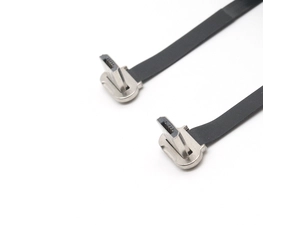
The right-angle plug turns the cable route immediately after the USB-C port. This can help when a straight connector would project toward a cover, bracket or narrow gap. The available clearance depends on the complete plug housing and the surrounding device structure, including any lip or recess around the port.
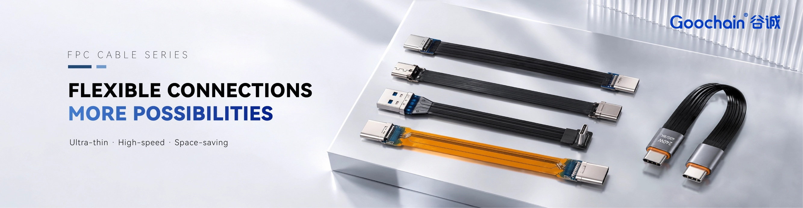
The FPC body can follow a defined route around an equipment mount or inside an enclosure. Typical integration tasks include linking an embedded USB-A host to a USB-C peripheral or arranging a data and charging connection where a conventional cable loop would take up useful space.
Choose the exit direction from a fixed view of the device port. A front-facing port photo and a side view of the housing help establish where the cable should run and whether the connector body will clear nearby features.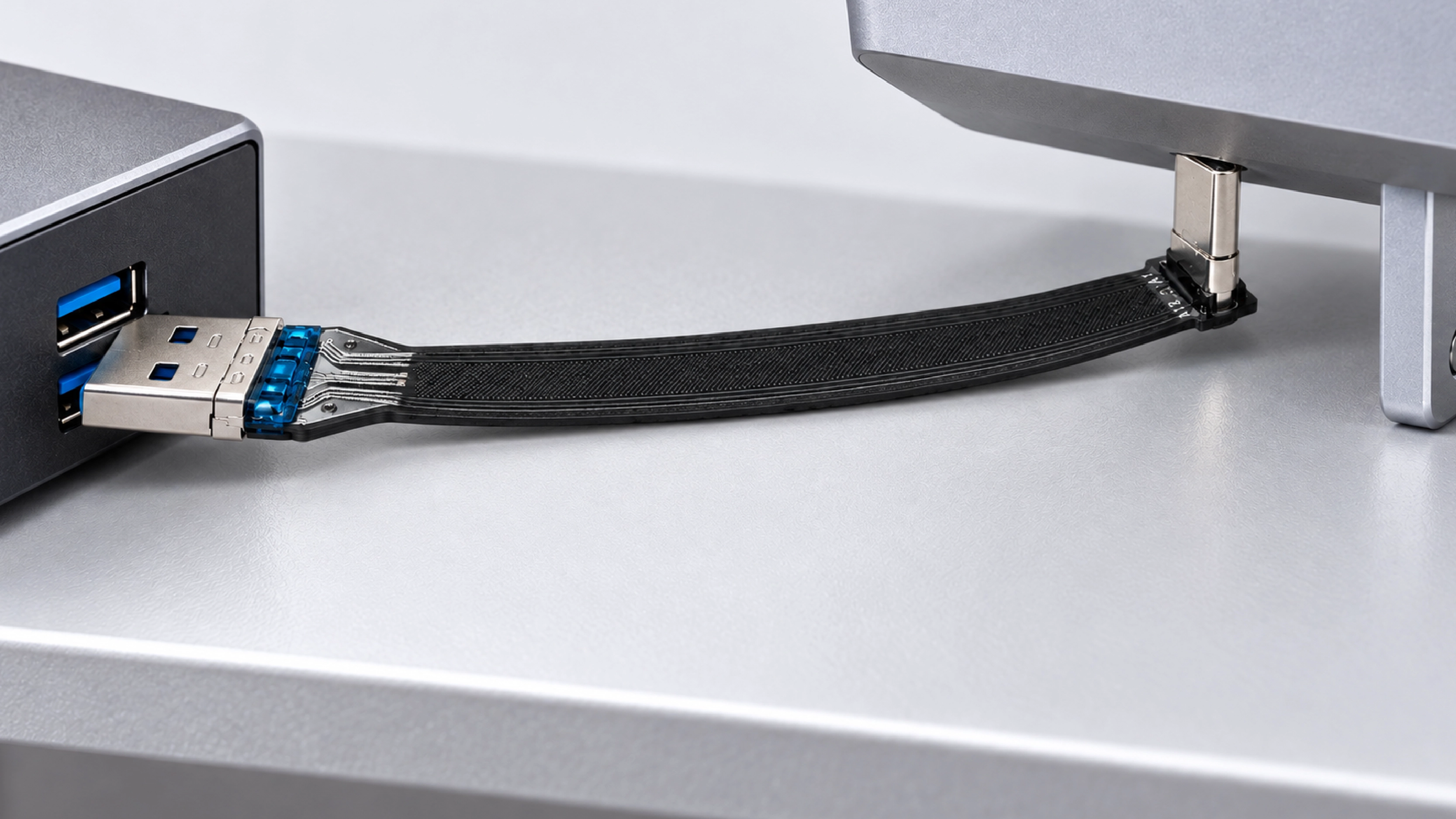
This model is the USB 2.0 configuration. The USB-C connector provides the device-side interface; its shape does not make this assembly a USB4 or higher-speed cable. If the equipment requires a different data rate, that requirement should be reviewed as a separately specified assembly.
For charging or combined data and power use, identify the USB-A source and the connected device. The power requirement must be matched to the source and cable design. USB-C PD Extended Power Range charging at 240W is not a feature of this USB-A-to-USB-C configuration.
As a USB-A to USB-C FPC cable manufacturer, Goochain can adjust the cable length, FPC route, device-side exit direction and connector housing arrangement to suit the installation. We support connector assembly, sample evaluation and final electrical inspection for OEM supply.
An installation sample allows the connector clearance and cable route to be checked with the actual equipment. Define whether the assembly must carry data, charging power or both, so the sample and production specification cover the required functions.
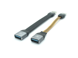
If your design needs to extend a USB-A port while retaining a USB-A socket, compare our USB-A male to female FPC extension cable. That product uses a different connector combination and has its own electrical specification.
For an OEM quotation, please provide:
Ask Goochain for a custom USB-A to USB-C FPC cable quotation with your layout and project requirements.
No. One end is USB-A male and the other is a 90-degree USB-C male plug. Both connector types are identified in the product specification.
This product is the USB 2.0 configuration. A different speed requirement should be quoted as a separately specified assembly.
Yes. Goochain can customize the cable exit to the installation. Define the direction from a fixed view of the device port and show the available space on each side.
No. USB-C PD Extended Power Range at 240W is not supported by this USB-A-to-USB-C configuration. Match the power requirement to the USB-A source, connected device and cable design.
Keep required fields minimal. Attach drawings/photos for accurate quoting.
Tip: A simple installation photo often saves 2–3 rounds of questions.
Quotation 1–2 days; development 15–20 days; mass production 20–25 days (project dependent).
Yes. Reference sample + requirements helps confirm drawings and test plan.
Depends on materials and complexity. We support prototypes and scalable mass production.


 English
 简体中文
简体中文  Deutsche
  Italian
  français
  Español
  Nederlands
  日本語
日本語  한국어
한국어  عربى
عربى  português
  Türk
Türk